No.18S111-03
17/70
STC-MBS500POE / STC-MCS500POE
Product Specifications and User’s Guide
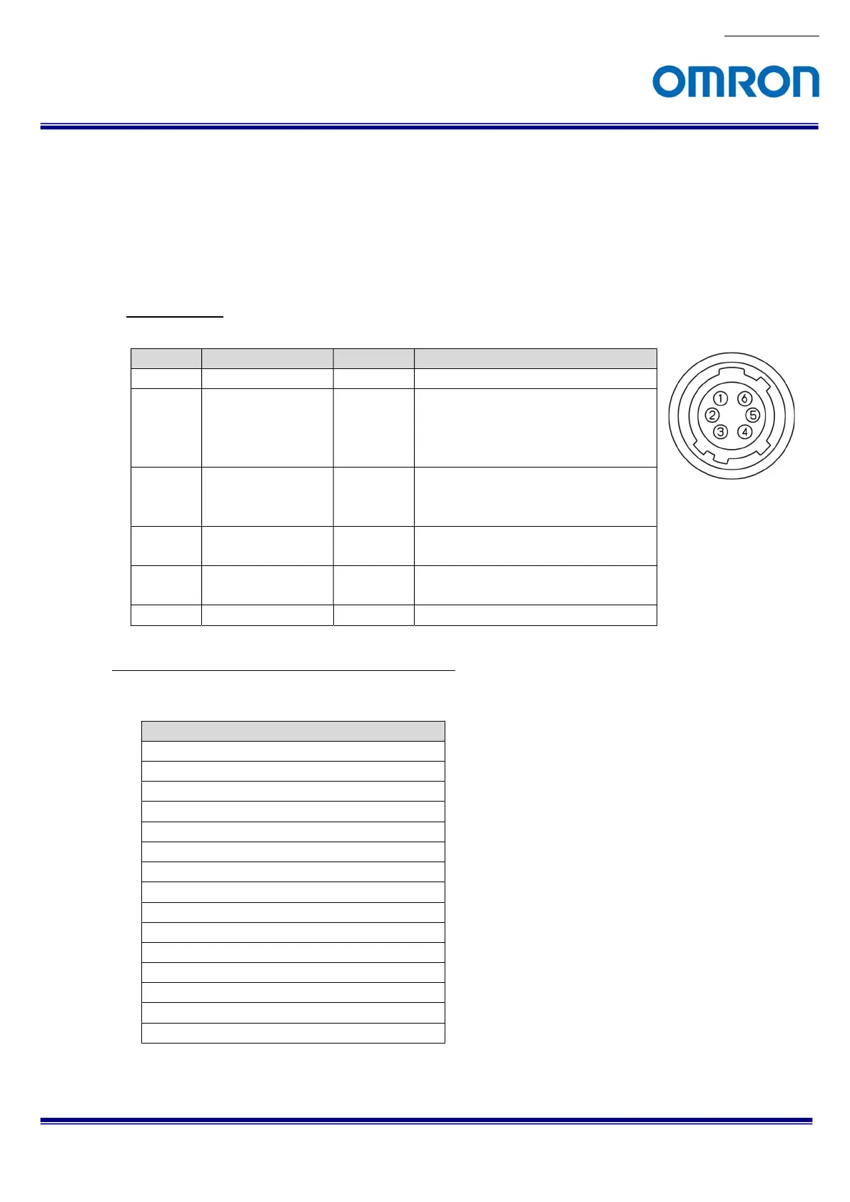
6.2 Power and Control Signal Connector
HR10A-7R-6PB (Hirose) or equivalent
This connector is for the power supply and input / output signals.
The power from this connector is priority power for camera when power supplies through this connector and
PoE at same time.
Please use HR10A-7P-6S (Hirose) or equivalent for cable.
Pin assignment
Configuration of Line2 (Pin No.3) and Line1 (Pin No.4)
Output signal can be assign by GenICam command.
.
Pin No.
Signal Name IN / OUT
Voltage
1 POWER IN IN +10.8 to +26.4 Vdc
2 Opto-isolated in
(Line0)
IN Low: Smaller than +1.0 V
High: +3.0 to +26.4 V
* Potential difference between
TRG_in and Opt. Isolated Common
3 Open Collector
GPIO
(Line2)
IN / OUT
+3.0 to +26.4 V / Open Collector
4 Opto-isolated out
(Line1)
OUT Open Collector
5 Opto-isolated
Common
IN
6 GND IN 0 V
GenICam
1) Frame Trigger Wait (Default for all output)
2) Frame Trigger Internal
3) Exposure Active
4) Acquisition Trigger Wait
5) Acquisition Trigger Internal
6) Sensor Read Out
7) Debounced Line 0
8) Debounced Line 2
9) User Output 1
10) User Output 2
11) Timer 0 Active
12) Software Signal 0
13) Software Signal 1
14) Logic Block 0
15) Pulse Per Second
 Loading...


