No.18S111-03
25/70
STC-MBS500POE / STC-MCS500POE
Product Specifications and User’s Guide
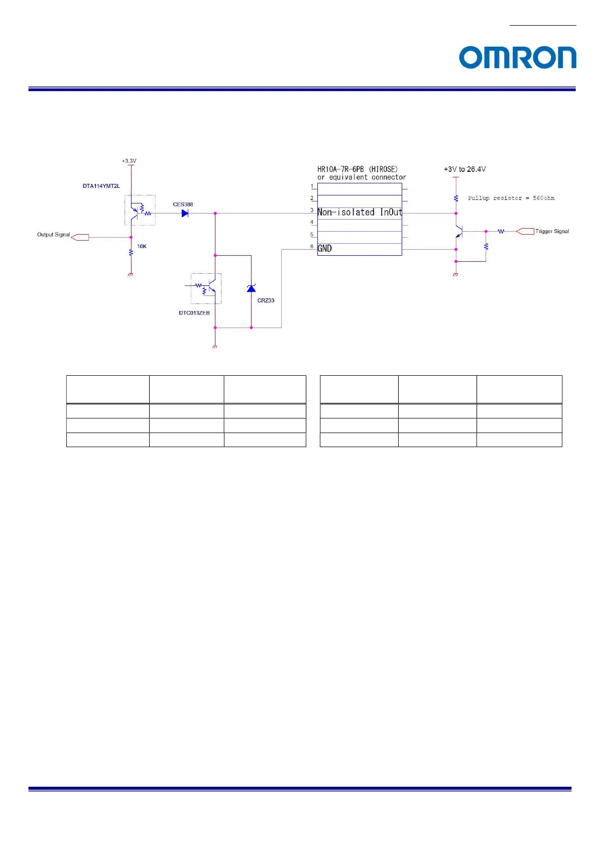
6.2.6.4 Measured External Trigger Signal Delay through Open Collector GPIO Port (Line 2)
Measurement circuit
Positive polarity trigger signal
Negative polarity trigger signal
Pull-up voltage
Tdelay
Minimum active
pulse duration
Pull-up voltage
Tdelay
Minimum active
pulse duration
+3.3 V 3.9 μseconds
6 μseconds
+3.3 V 0.6 μseconds
6 μseconds
+12 V 3.8 μseconds
3 μseconds
+12 V 0.8 μseconds
3 μseconds
+24 V 2.2 μseconds
2 μseconds
+24 V 0.8 μseconds
2 μseconds
Note. Please use this measured delay as reference. The delay time may fluctuate depending on transistor variation,
pull-up voltage and pull-up resister.
 Loading...


