4-126
4-3 Functions When Option PG Board (3G3AX-PG01) Is Used
4
Functions
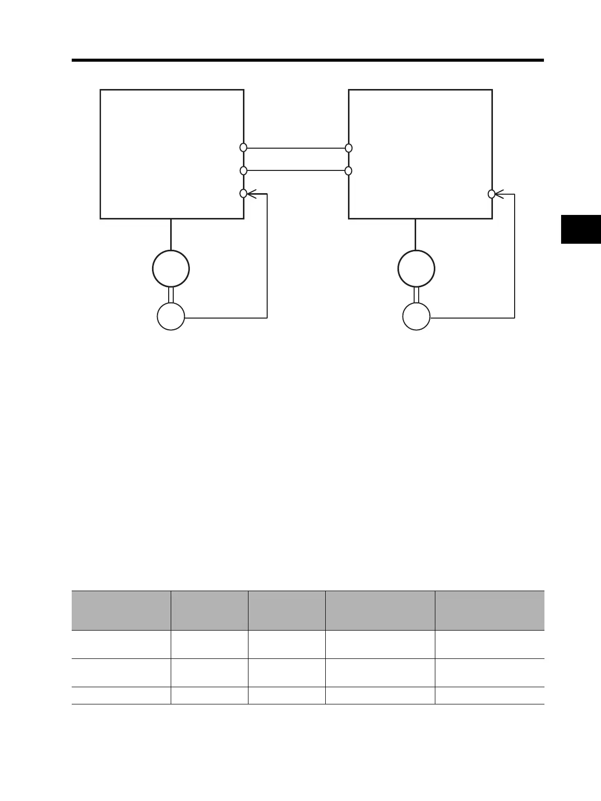
Example: Synchronous Operation
For the Inverter (master Inverter) on the main motor side, you can select either the speed control or
pulse train position control mode.
For the Inverter (slave Inverter) on the sub motor side, you need to select the pulse train position
control mode.
Configuration Example
•Main motor : Number of encoder pulses = 1024
•Sub motor : Number of encoder pulses = 3000
•Main motor rpm:Sub motor rpm = 2:1
For operation under the above conditions, set the following data in the slave Inverter.
Pulse train mode selection (P013) : 00 (pulse with 90° phase difference)
Electronic gear setting position selection (P019) : 01 (REF)
Electronic gear ratio numerator (P020) : 3000
Electronic gear ratio denominator (P021) : 1024 × 2 = 2048
The following shows an example of the ratio of slave rpm to master rpm depending on the P019 to
P021 settings.
(Note that the same number of encoder pulses (1024 pulses) should be set on both Inverters.)
Master Inverter
AP, BP
AN, BN
EG5
EAP, EBP
EAN, EBN
SAP, SBP
SAN, SBN
EG5
EAP, EBP
EAN, EBN
Slave Inverter
M
EC
Main
motor
M
EC
Sub
motor
Electronic gear setting
position selection
(P019)
REF
(Position
command side)
REF
(Position
command side)
FB
(Position feedback side)
FB
(Position feedback side)
Electronic gear ratio
numerator (P020)
1024 2048 1024 2048
Electronic gear ratio
denominator (P021)
2048 1024 2048 1024
Slave rpm/Master rpm 1/2 2 2 1/2
 Loading...


