7-22
7-3 Options
7
Specifications
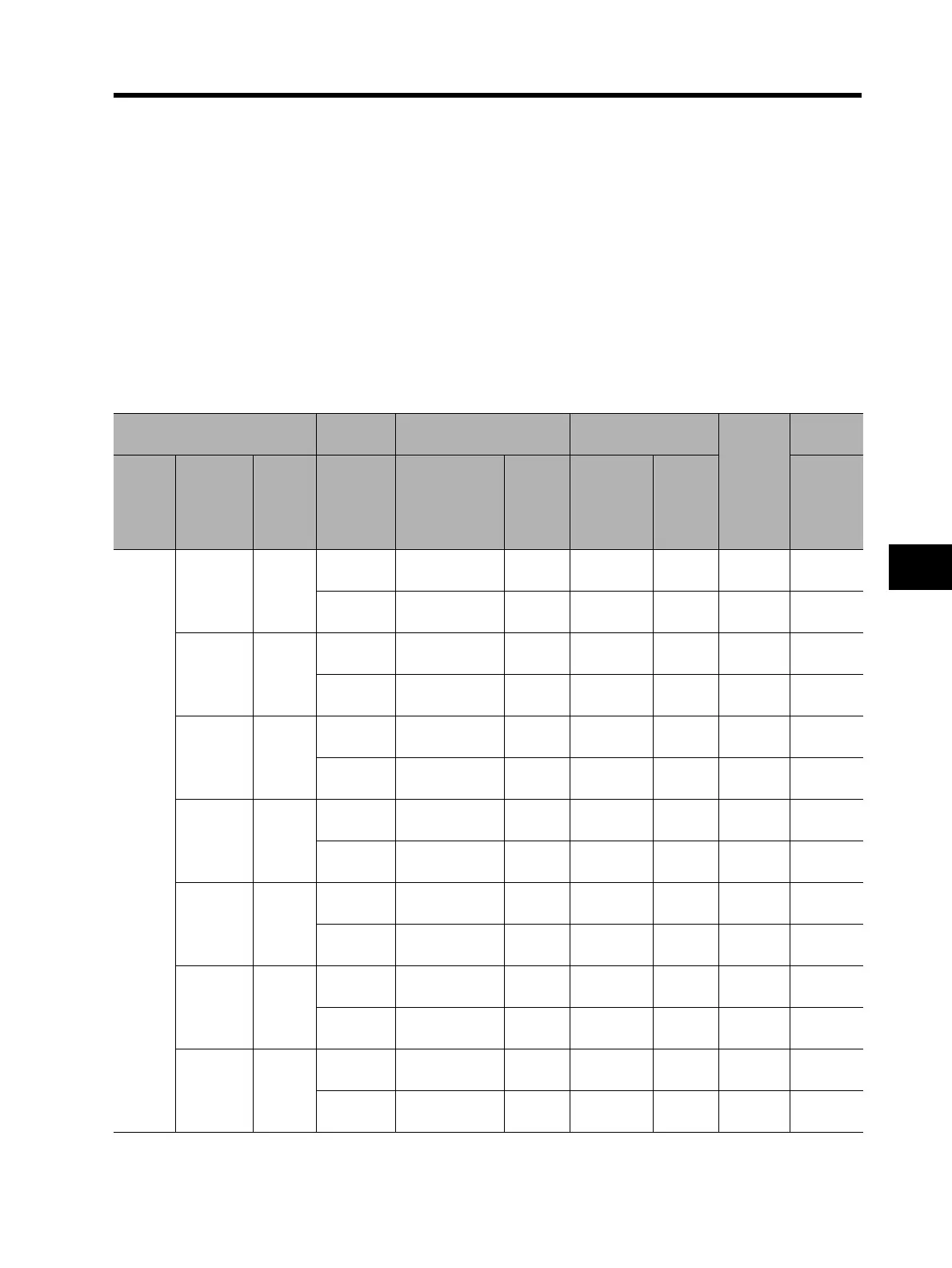
Simplified Selection Table for Regenerative Braking Unit and Braking Resistor
(1) Inverter specifications (choose voltage, capacity, and model)
The content noted in the table assumes the case of combining one Inverter and one motor of the
same capacity.
(2) Select the %ED.
Use the %ED that is equivalent to or lower than the value shown.
(3) This shows the model and number of regenerative braking units and braking resistors.
(4) This provides a summary of the connection configuration of the regenerative braking unit and
braking resistor.
Refer to pages 7-22 to 7-28.
(5) The specified conditions contain restrictions. Make sure there are not any issues
(1) Inverter
(2) Usage
conditions
(3) Regenerative braking
unit
(3) Braking resistor
(4)
Connection
(5)
Restrictions
Voltage
Max.
applicable
motor
capacity
(kW)
Model
%ED
(%)
Model
Number
of units
Model
Number
of units
Allowable
continuous
braking
time (s)
200-V
Class
0.4
3G3RX
-A2004
3.0%
Built-in braking
resistor circuit
3G3AX-
RBA1201
1120
10.0%
Built-in braking
resistor circuit
3G3AX-
RBB2001
1130
0.75
3G3RX
-A2007
3.0%
Built-in braking
resistor circuit
3G3AX-
RBA1201
1120
10.0%
Built-in braking
resistor circuit
3G3AX-
RBB2001
1130
1.5
3G3RX
-A2015
3.0%
Built-in braking
resistor circuit
3G3AX-
RBA1202
1120
10.0%
Built-in braking
resistor circuit
3G3AX-
RBC4001
1110
2.2
3G3RX
-A2022
3.0%
Built-in braking
resistor circuit
3G3AX-
RBB3001
1130
10.0%
Built-in braking
resistor circuit
3G3AX-
RBC4001
1110
3.7
3G3RX
-A2037
3.0%
Built-in braking
resistor circuit
3G3AX-
RBB4001
1120
10.0%
Built-in braking
resistor circuit
3G3AX-
RBC6001
1110
5.5
3G3RX
-A2055
3.0%
Built-in braking
resistor circuit
3G3AX-
RBB3001
2330
10.0%
Built-in braking
resistor circuit
3G3AX-
RBC40
0
1
2310
7.5
3G3RX
-A2075
3.0%
Built-in braking
resistor circuit
3G3AX-
RBB4001
2320
10.0%
Built-in braking
resistor circuit
3G3AX-
RBC6001
2310