3-1SectionDIP Switch Setting
13
Dip Switch Settings
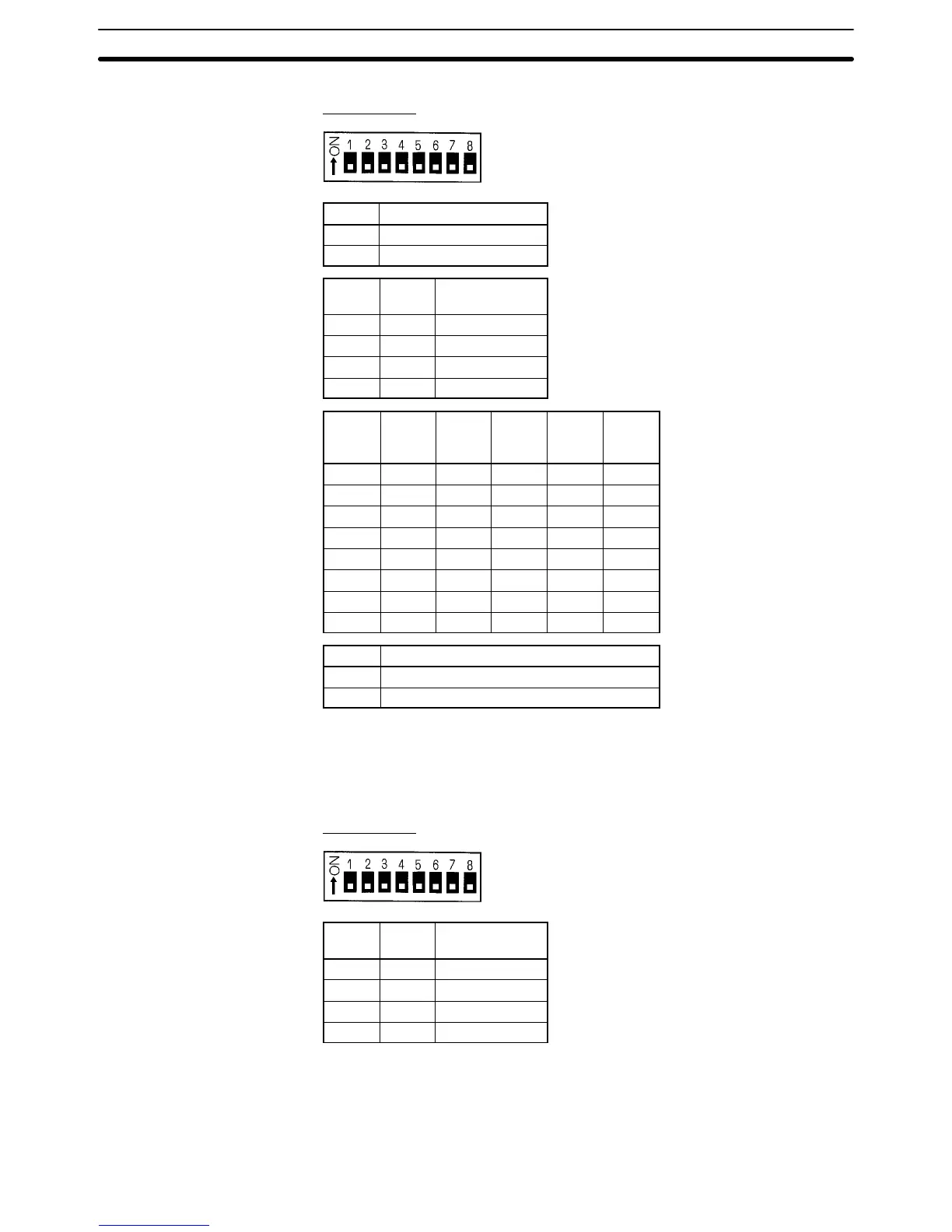
DIP Switch 1
SW1 Display mode
0 Error Display Mode
1 I/O Display Mode
SW2 SW3 Transmission
speed (bps)
0 0 2,400
0 1 4,800
1 0 9,600
1 1 19,200
SW4 SW5 SW6 Data
length
(bit)
STOP
bits
(bit)
Parity
type
0 0 0 7 2 Even
0 0 1 7 2 Odd
0 1 0 7 1 Even
0 1 1 7 1 Odd
1 0 0 8 2 None
1 0 1 8 1 None
1 1 0 8 1 Even
1 1 1 8 1 Odd
SW7 Local communications mode setting
1 Speed priority mode
0 Distance priority mode
The setting of SW7 is only valid if the EEPROM-type (batteryless-type) Data
Carrier (DC) is accessed. The setting of SW7 does not work with the SRAM-type
(battery-type) DC. Refer to the R/W Head Manual and Data Carrier Manual for
details. SW7 must be set to OFF when the V620 is used.
SW8 is not used. (Keep it switched OFF.)
DIP Switch 2
SW1 SW2 Synchronous
condition
0 0 OFF (LL level)
0 1 ON (HL level)
1 0 Trailing edge
1 1 Leading edge
SW3 through SW7 are not used. (Keep them switched OFF.)
Before setting the switches, be sure to turn OFF the Power to the ID Controller.
The switch settings are read when Power is switched ON. To change the switch
settings, turn OFF the Power once, change the setting, and then turn ON the
Power again.