2-1SectionNames and Functions of Parts
8
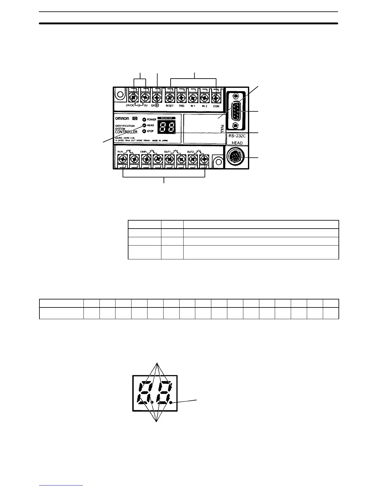
2-1 Names and Functions of Parts
Power
terminals
External input terminals
(4 points, 1 common points)
Protective
conductor
terminal
Switch cover
RS-232C
interface
connector
Monitor display
R/W Head connector
External output terminals
(4 points, independent common)
LED operation
indicators
V600-CD1D-V3
Operation Indicators
Name Color Function
POWER Green Lit when power is supplied.
HEAD Yellow Lit when R/W Head is executing communications processing.
STOP Red Lit when an error (such as CPU error or memory error) has
occurred or when external reset signal has been input.
Monitor Display
1, 2, 3... 1. Error Display Mode: Displays end code of command processing. The end
code is displayed as a 2-digit hexadecimal number.
Hexadecimal 0 1 2 3 4 5 6 7 8 9 A B C D E F
Indication
0 1 2 3 4 5 6 7 8 9 a b c d e f
2. I/O Display Mode: Displays the ON/OFF status of the I/O terminal and indi-
cates the occurrence of an error.
Indication of input status
(From the left: RESET, TRIG, IN1, and IN2)
Error indication
Indication of output status
(From the left: RUN, CMPL, OUT1, and OUT2)
Note The Display Mode is set by the internal DIP switch.