3-6SectionRS-232C Interface Connection
20
Solderless I/O Terminal
The I/O terminals employ M3.5 screws. When using solderless terminals, use
the following:
7.0 max.
7.0 max.
(M3.5)
Keep the tightening torque to within 8 kg-cm.
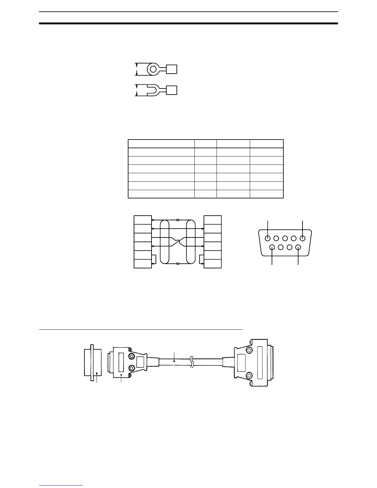
3-6 RS-232C Interface Connection
Signal name Abbr. I/O Pin no.
Ground GR ––– 1
Signal ground SG ––– 9
Send data SD Output 2
Receive data RD Input 3
Request to send RS Output 4
Clear to send CS Input 5
GR
SG
SD
RD
RS
CS
FG
SG
SD
RD
RS
CS
ID Controller Host computer
(Shielded cable)
51
96
Note 1. Ground the shielded cable at either the ID Controller side or host computer
side to prevent malfunctioning. The above left figure shows an example of
shielded cable grounding at the ID Controller side.
2. Internally short-circuit pins 4 (RS) and 5 (CS).
Assembly and Connection of Communications Connector
Plug
XM2A-0901*
(supplied as an
accessory)
(OMRON)
ID Controller side
Cable
Host computer side
Hood
XM2S-0911*
(supplied as an
accessory)
(OMRON)
Recommended cable
5PX28AWG, 7 dia.
*Use the accessory connector as the communications connector. Separately
prepare the connecting cable and the connector of the host computer. The con-
nector of the ID Controller is made by OMRON and takes countermeasures
against EMI.