3-6SectionRS-232C Interface Connection
21
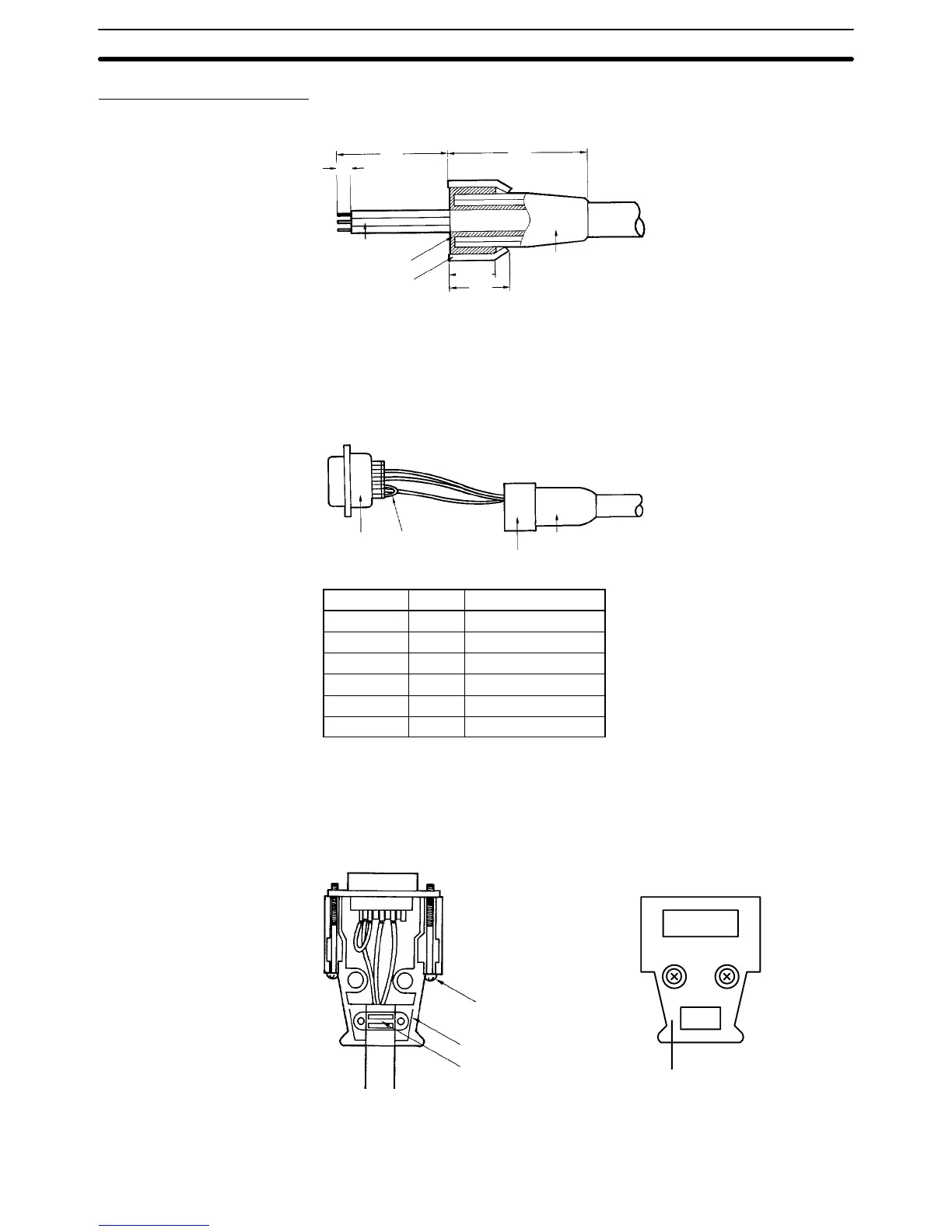
Assembly of Connector
1, 2, 3... 1. Process the ends of the cables.
12
40 35
5
Core
Shield mesh
Shield tape
Cable bushing
10±1
• Run the cable bushing through the cable in advance.
• Loosen the shield mesh and return it on the cable bushing. At this time,
keep the returning length to about 10 mm.
• Wind the shield tape onto the shield mesh.
2. Solder the cores of the cables to the pins.
Plug
Crossover line
Cable bushing
Aluminum tape
Pin no. Abbr. Signal name
1* GR Frame ground
9 SG Signal ground
2 SD Send data
3 RD Receive data
4** RS Request to send
5** CS Capable to send
*GR is grounded to the connector hood and is therefore connected to the GR of
the ID Controller through the connector hood. It is therefore unnecessary to con-
nect GR to pin 1.
**Short-circuit pins 4 (RS) and 5 (CS) with a crossover line.
3. Set the plug to the housing A2 of the hood and clamp the aluminum tape.
Lock screw (2-M2.6)
Housing A2
Cable clamp
Housing B2
4. Set the two connector tightening screws and attach housing B2 to A2 to
complete the connector.