3-5SectionWiring
18
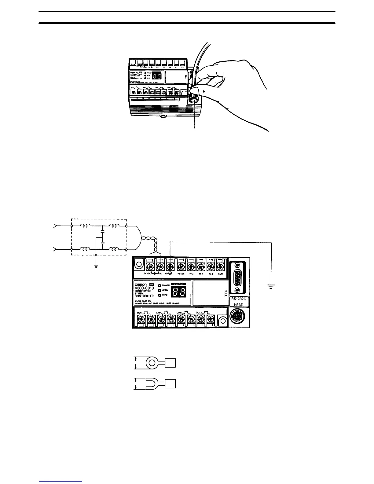
To Disconnect
Ring
To remove the connector, pull it straight out while holding the ring.
Note The connector must not be pulled while holding the rubber mold. If an
excessive force is applied to the cable, the cable may break or be-
come damaged.
3-5 Wiring
Power Supply Line and Ground Line
Grounding at less than 100 Ω
Line filter
M3.5 screws are used for the Power and ground terminals. In the case of solder-
less terminals, use the following. Keep the tightening torque to within 8 kg-cm.
7.0 max.
7.0 max.
M3.5
Supply 24 VDC to the ID Controller. Make sure that the voltage fluctuation is
within the range of 20.4 to 26.4 VDC (24 VDC
+10%
/
–15%
).
The countermeasures against noise provided to the IC Controller is sufficient to
suppress noise superimposed on power lines. However, by supplying power
through a filter, noise can be substantially reduced.
The power dissipation of the ID Controller is 7.2 W maximum with a maximum
configuration. Note, however, that an inrush current of about 20 A (at 24 VDC)