28
Section 2 Wiring
RFID System
Operation Manual
Section 2
Installation and Wiring
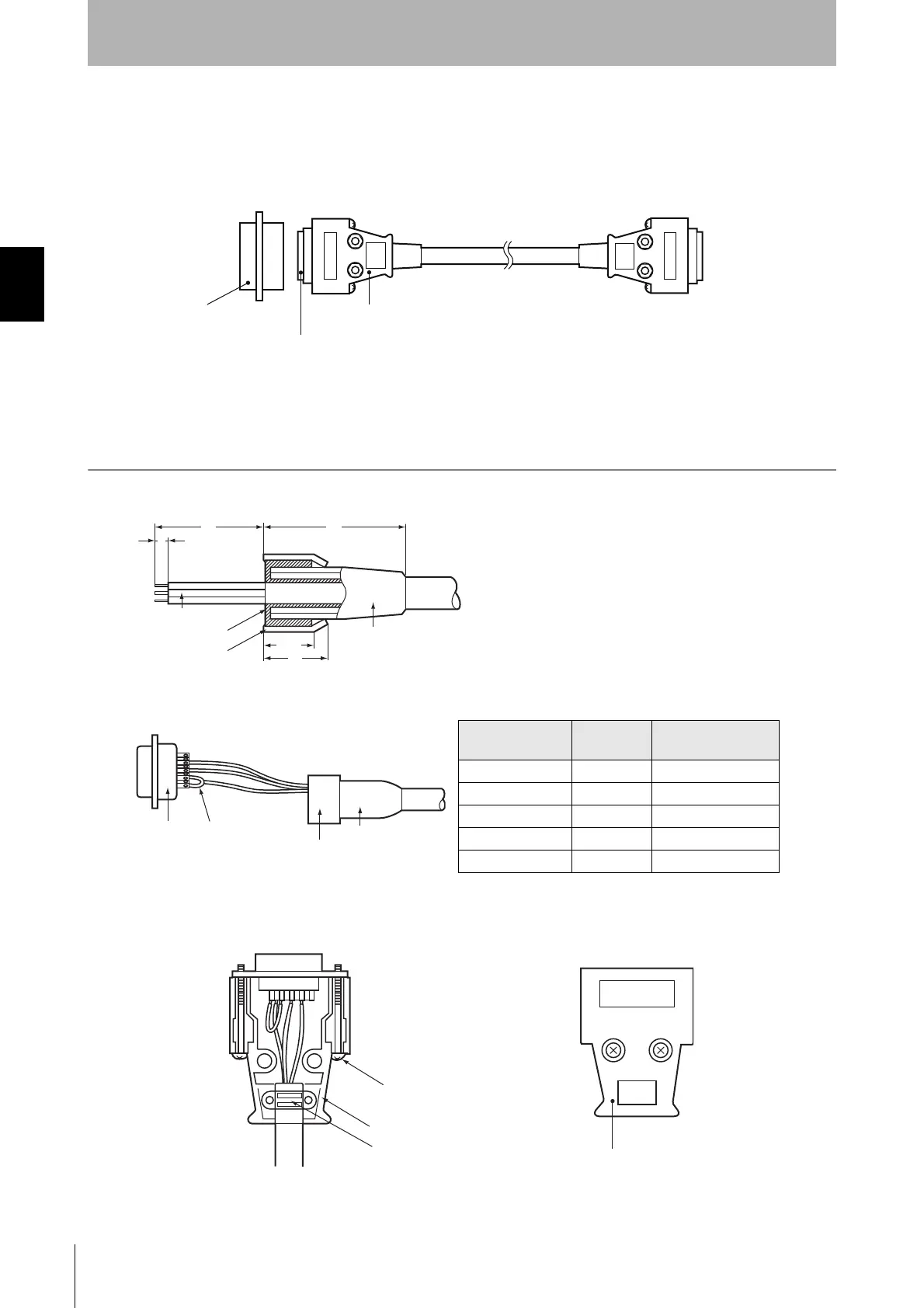
■ Assembling and Connecting the Communications Connector
Use the communications connector provided with the ID Controller. The user must provide the con-
necting cable and the host computer connector. The ID Controller connector is manufactured by
OMRON and is protected from electromagnetic interference (EMI).
■
Connector Assembly
1. Prepare the end of the cable.
• First pass the cable through the cable bushing.
• Unwind the shielded braid and turn the braid back over the cable
bushing. Turn approximately 10 mm of the shielded braid back
over the cable bushing.
• Wrap the lines with sealing tape.
2. Solder conductor lines and plug pins.
3. Set the hood housing A2 onto the plug, and secure the aluminum tape section with a clamp.
4. Tighten the two connector holding screws, and then cover the assembly with housing B2 to complete
the connector.
Controller end
OMRON
XM3B-0922-111
Socket
OMRON
XM2S-0911
Hood
Host device end
OMRON
XM3A-0921
Plug
Note: Hood and Plug of the following are not attached.
Hood: XM2S-0911 equivalent
Plug: XM3A-0921 equivalent
40
35
5
Conductor lines
Shield braid
Shield tape
10
12
Cable bushing
Pin No.
Abbrevia-
tion
Signal name
9 SG Signal ground
2 SD Send data
3 RD Receive data
4 (See note.) RS Request to send
5 (See note.) CS Can send
Note Short pins 4 (RS) and 5 (CS) with a crossover
line inside the connector.
Plug Crossover
Aluminum tape
Cable bushing
Lock screw (two
screws, M2.6)
Housing A2
Cable clamp
Housing B2

 Loading...


