27
RFID System
Operation Manual
Section 2 Wiring
Section 2
Installation and Wiring
RS-232C Port
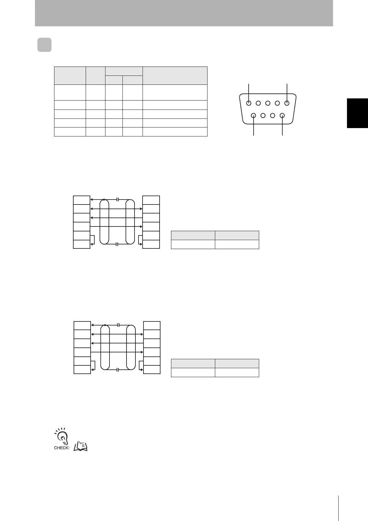
■ Pin Arrangement
■ Connecting to the Host Device
■ Connection Example to OMRON PLC
Recommended Cable
■
Connection Example to DOS Computer (IBM PC/AT or Compatible)
(This example uses a 9-pin D-Sub connector.)
Recommended Cable
For 1:N connections, refer to Connecting between ID Controllers (1:N Connections).
p.31
Model Manufacturer
XW2Z-@@@TOMRON
Note 1. Ground the shield at the host device to prevent malfunctions.
2. Pins 4 (RS) and 5 (CS) are connected inside the connector.
Model Manufacturer
XW2Z-@@@S-V OMRON
Note 1. The ID Controller connector on the interface cable is male
and the computer connector is female.
2. Ground the shield at the host device to prevent malfunctions.
Pin No.
Abbre-
viation
Signal direction
Signal name
Input Output
9 SG --- ---
Signal ground or common
return line
2SD---❍ Send data
3RD❍ --- Receive data
4RS---❍ Request to send
5CS❍ --- Can send
51
96
(The example at the left is for connecting a shielded cable to the host device.)
• Pin Arrangement
ID Controller
Host device
Shield
GR
SG
SD
RD
RS
CS
GR
SG
RD
SD
RS
CS
ID Controller
IBM PC/AT or compatible
(Shield)
GR
SG
SD
RD
RS
CS
GR
SG
RD
SD
RS
CS

 Loading...


