31
RFID System
Operation Manual
Section 2 Wiring
Section 2
Installation and Wiring
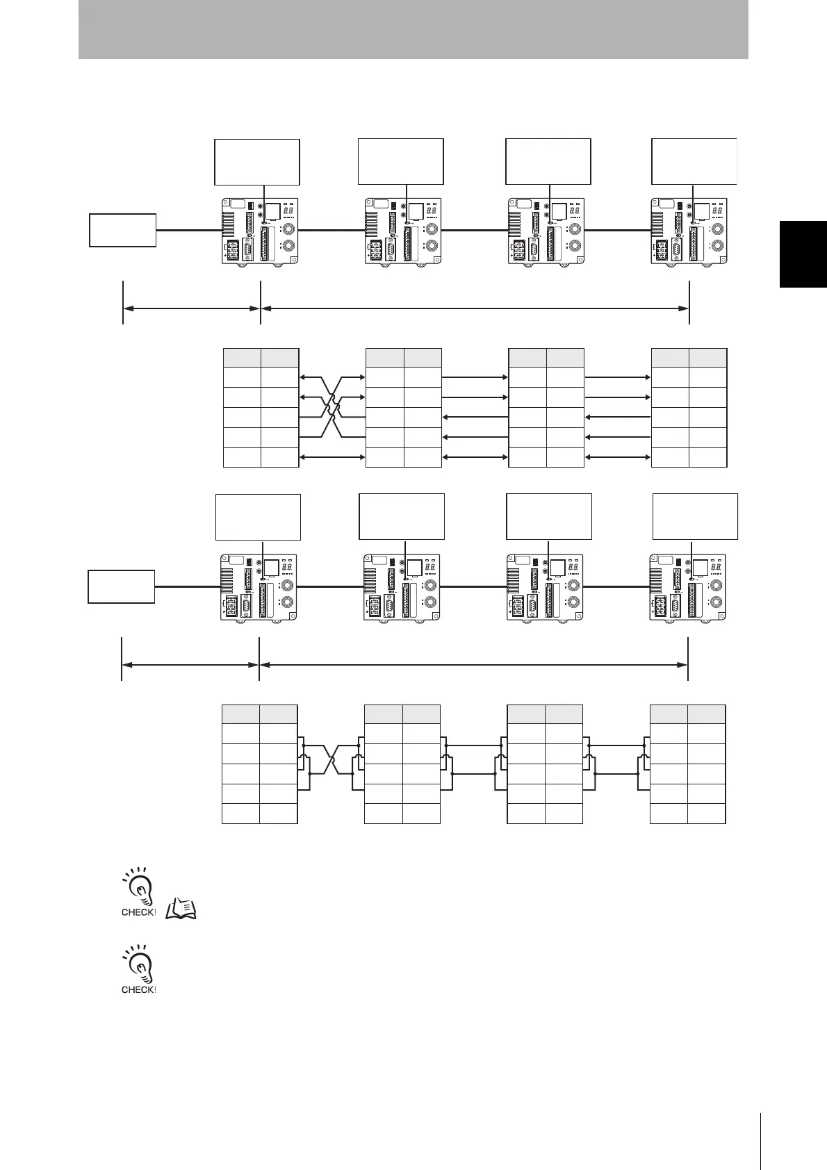
■ Connecting between ID Controllers (1:N Connections)
■ RS-232C Host Device Connection
Note: Using RS-485 is possible by shorting pins 1 and 3 and pins 2 and 4, and changing the setting to RS-485.
For the RS-232 connection between the host device and ID Controller, refer to Connecting to the Host Device.
p.27
If RS-232C communications are used first by the ID Controller, receiving RS-422/RS-485 communications will be pro-
hibited. If RS-422/RS-485 communications are used first by the ID Controller, receiving RS-232C communications will
be prohibited. It is thus necessary to turn OFF the power supply before changing the ID Controller system configuration.
ID ControllerID Controller
RS-422
ID Controller
RS-422
ID Controller
RS-422
Pin No.
Abbreviation
1RDA(−)
2 RDB(+)
3SDA(−)
4 SDB(+)
5SG
SW6: OFF
Terminating resistance
not connected.
Pin No.
Abbreviation
1RDA(−)
2 RDB(+)
3SDA(−)
4 SDB(+)
5SG
Pin No.
Abbreviation
1RDA(−)
2 RDB(+)
3SDA(−)
4 SDB(+)
5SG
Pin No.
Abbreviation
1RDA(−)
2 RDB(+)
3SDA(−)
4 SDB(+)
5SG
Host device
RS-232C
SW6: ON
Terminating
resistance connected.
Maximum length: 15 m Maximum total length: 500 m
SW6: OFF
Terminating resistance
not connected.
SW6: ON
Terminating
resistance connected.
ID ControllerID Controller
RS-485
ID Controller
RS-485
ID Controller
RS-485
1RDA(−)
2 RDB(+)
3SDA(−)
4 SDB(+)
5SG
1RDA(−)
2 RDB(+)
3SDA(−)
4 SDB(+)
5SG
1RDA(−)
2 RDB(+)
3SDA(−)
4 SDB(+)
5SG
1RDA(−)
2 RDB(+)
3SDA(−)
4 SDB(+)
5SG
RS-232C
SW6: OFF
Terminating resistance
not connected.
SW6: ON
Terminating
resistance connected.
Maximum length: 15 m Maximum total length: 500 m
SW6: OFF
Terminating resistance
not connected.
SW6: ON
Terminating
resistance connected.
Pin No.
Abbreviation
Pin No.
Abbreviation
Pin No.
Abbreviation
Pin No.
Abbreviation
Host device

 Loading...


