34
Section 2 Wiring
RFID System
Operation Manual
Section 2
Installation and Wiring
USB Port
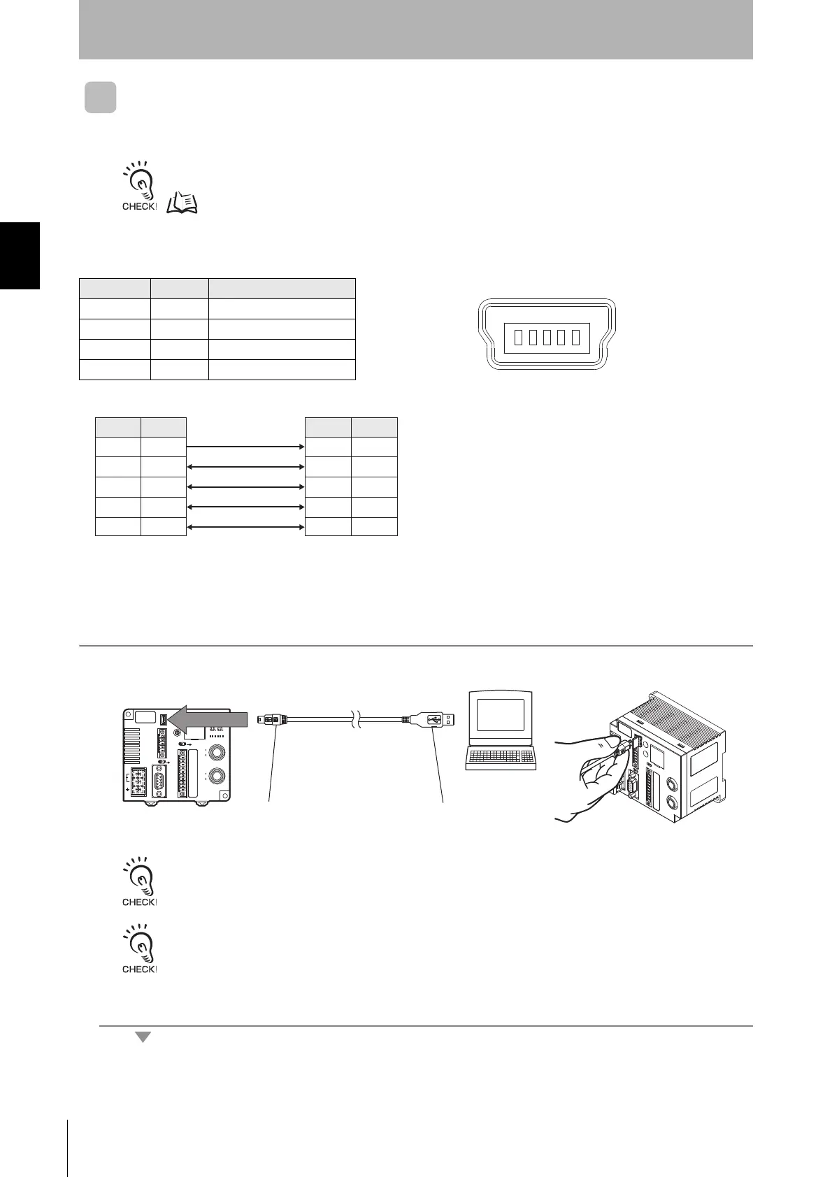
The host device can be connected using an USB cable (series A and mini USB series B connectors).
The USB port is not used for control operations. When constructing a system, always use the RS-232C or RS-422/RS-
485 port.
p.16
■ Pin Arrangement
■ Inserting and Removing the Connector
1. Connecting the Mini USB Series B Connector to the ID Controller
The connectors are capped when shipped from the factory. If the USB connector is not used, leave the cap in place to
protect against dust, dirt, and static electricity.
Removing the Connector
Hold onto the base of the connector pull it straight out. If the connector is difficult to remove, hold the ID Controller and
pull the connector off.
Pin No. Name Description
1 VBUS Power supply
2D USB data ()
3 D+ USB data (+)
5 GND Ground
Pin No.
123 45
• Pin Arrangement
Abbreviation
D
Pin No.
1
2
3
4
-
VBUS
D +
GND
FG
D
Pin No.
1
2
3
5
-
VBUS
D +
GND
FG
Abbreviation

 Loading...


