96
SECTION 5
When SECS is Not Used
CIDRW System
User’s Manual
SECTION 5
Troubleshooting
• Amplifier Unit error
Check the status of the indicator LEDs after transmission of the test command.
After taking appropriate corrective action, restart the Amplifier Unit, send the test command again and
check again.
• If there is no response to the command:
Check the status of the indicator LEDs after transmission of the test command.
After taking appropriate corrective action, restart the Amplifier Unit, send the test command again and
check again.
Method using RS signal control at the host device
In a 1:N connection using Link Units, the RS signals generated from the host device by normal control must be input as
CS signals. Turn the RS signals OFF within 15 ms after the completion of data transmission. Correct communications
will not be possible without this control.
• If there is a response to the command:
Check the status of the indicator LEDs after transmission of the test command.
After taking appropriate corrective action, restart the Amplifier Unit, send the test command again and
check again.
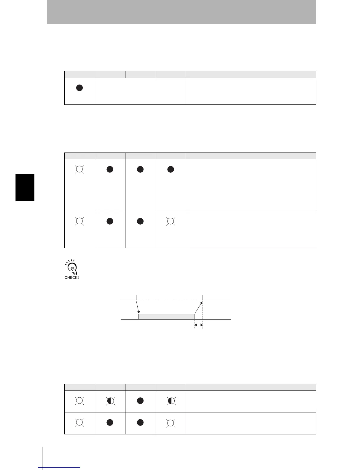
RUN COMM NORM ERROR Main check points
—
(If RUN is OFF, the status of the other indica-
tor LEDs can be ignored.)
• Influence of background noise (change installation position)
• Amplifier Unit power supply
If the error cannot be resolved after checking, the Amplifier Unit
may be damaged.
RUN COMM NORM ERROR Main check points
• Amplifier Unit baud rate settings
• Node numbers of the Amplifier Units (do not match the node
number in the test command)
• Connection and wiring of the cable between the host device
and Amplifier Unit
• OFF timing of the RS signals between the host device and
Amplifier Unit
• Routing of each cable (influence of background noise)
If the error cannot be resolved after checking, the Amplifier Unit
may be damaged.
• Amplifier Unit baud rate settings
• Connection and wiring of the cable between the host device
and Amplifier Unit
• Routing of the cables (influence of background noise)
• OFF timing of the RS signals between the host device and
Amplifier Unit
• FCS (frame check sequence) calculation method
RUN COMM NORM ERROR Main check points
• Node numbers of the Amplifier Units (The same number is set
for more than one unit)
If the error cannot be resolved after checking, the Amplifier
Unit may be damaged.
There is a mistake in the command format (number of charac-
ters, character code, etc.).
(Lights once)
SD at host device
RS at host device
ON only during data transmission from the host device
Within 15 ms
(Lights once)