15
CIDRW System
User’s Manual
SECTION 1
Component Names and Functions
SECTION 1
Product Outline
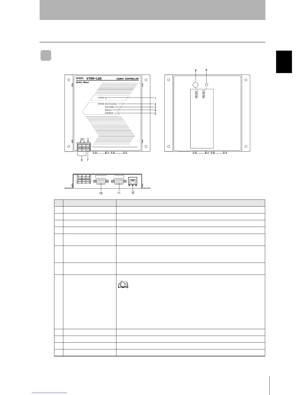
Component Names and Functions
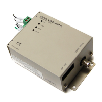
CIDRW Controller V700-L22
No. Name Function
1 Power indicator (green) An LED that indicates whether the power is ON or OFF. Lit while the power is ON.
2 OPERATING indicator (green) Lit while the CIDRW system status model is operating.
3 ALARMS indicator (green) Lit when the status in "Alarm Status" of the CIDRW system is Alarm (1).
4 BUSY indicator (green) Lit when the status in "Operational Status" of the CIDRW system is BUSY.
5 ERROR indicator (red) When a processing error is detected (when SSACK is other than NO), this indicator is lit
for 50 ms.
6 24 VDC power supply termi-
nals
(with cover)
Connect to the 24 VDC power supply.
7 Frame ground terminal
(with cover)
The grounding wire is connected here. (Ground to 100 Ω or less)
8 MODE switch Used to select the mode of operation.
Refer to page 44.
0: Normal Operation mode. When mounting the Controller, set the switch to this posi-
tion.
3: Setting mode, selected to set information such as the communication conditions.
When the switch on the bottom face of the Controller cannot be accessed, the opera-
tion mode can be changed from the host device while the switch is left at the 0 set-
ting.
1 - 2, 4 - 7:
Setting prohibited
9 RESET switch Restarts the CIDRW Controller.
10 SECS port Port for connecting the host device. Conforms to SECS I/II.
11 ID port An Amplifier Unit or Link Unit is connected here.
12 Maintenance port (with cover) Not used. Do not remove the cover.
RS-232C
SECS ID
MAINTENANNCE