104
SECTION 6
System Configuration Examples
CIDRW System
User’s Manual
SECTION 6
Appendix
System Configuration Examples
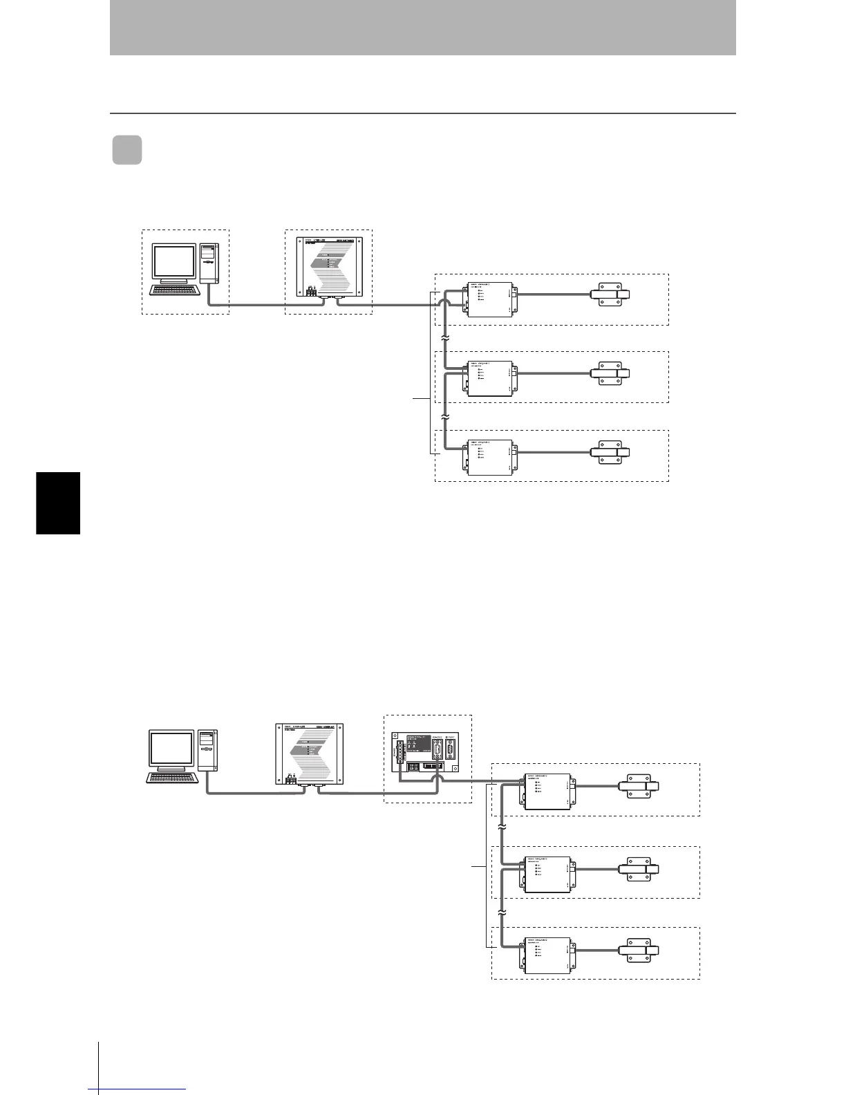
When SECS is Used
Communication with the host device is possible using the SECS protocol.
With the above system configuration, the Amplifier Unit connected directly to the CIDRW Controller
converts signals from RS-232C to RS-485. If this Amplifier Unit is removed, communications will not be
possible with the other Amplifier Units. If the Amplifier Unit connected directly to the CIDRW Controller
must be removed while the system is operating, insert a Link Unit (V700-L11) between the CIDRW
Controller and the first Amplifier Unit. If an Amplifier Unit on the end of the network is removed, be sure
to turn ON the terminating resistance on the Amplifier Unit that will end up on the end of the network
while the Amplifier Unit is removed.
Host
These are antennae for
reading the carrier IDs
from the ID Tags and
writing the carrier IDs.
These are units that
control a CIDRW Head.
Up to 31 units can be
connected.
This is e.g. a host,
or equipment con-
troller.
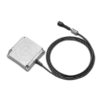
CIDRW Head
V640-HS62
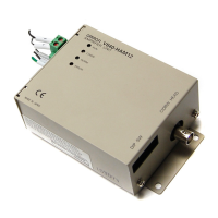
Amplifier Unit
V640-HAM12
CIDRW Controller
V700-L22
Multiple Amplifier Units
are controlled in
response to commands
(SECS) from the host
device.
RS-232C
SECS I/II
Max. 50 m
RS-485
RS-232C
RS-232C
SECS I/II
RS-232C
Link unit
V700-L11
Just the relevant Amplifier Unit can be
removed and replaced while the power
remains on.
Max. 50 m
RS-485
Up to 31 units can be connected.