16
SECTION 1
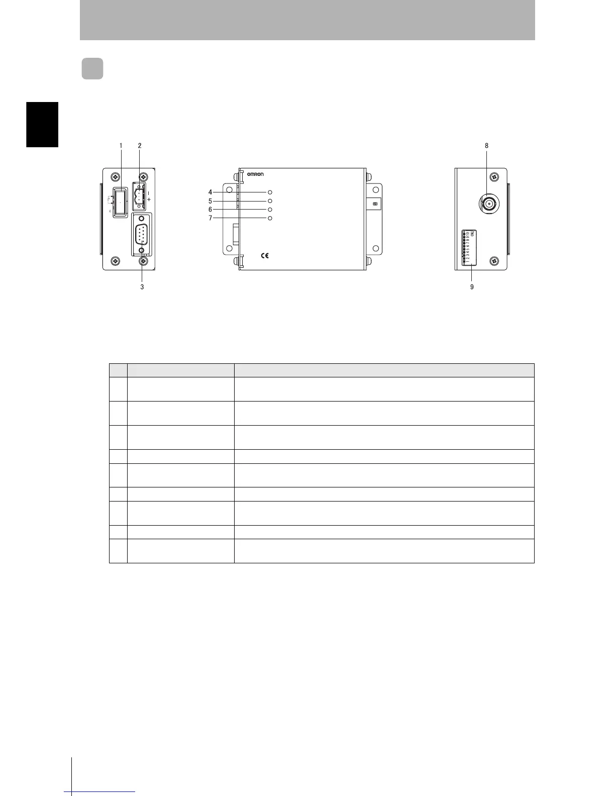
Component Names and Functions
CIDRW System
User’s Manual
SECTION 1
Product Outline
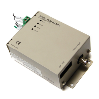
Amplifier Unit V640-HAM12
No. Name Function
1 Dedicated power supply con-
nector
Connect to the 24 VDC power supply.
2 RS-485 port When using multiple CIDRW Heads, connect this to the RS-485 port of another Amplifier
Unit or to the multi-connection port of a Link Unit.
3 RS-232C port Connected to a CIDRW Controller or a host device.
Uses the OMRON proprietary communications protocol.
4 RUN indicator (green) Turns ON when the Amplifier Unit is in normal operation.
5 COMM indicator (yellow) Turns ON during communications with the host device or during communications with an
ID Tag.
6 NORM indicator (green) Turns ON when the communications finish with no error.
7 ERROR indicator (red) Turns ON when an error occurs during communication with the host device, or during
communication with an ID Tag.
8 CIDRW Head connection port A CIDRW Head is connected here.
9 Setting DIP switches Used to set the node number, the communications conditions, and the RS-485 terminal
resistance.
V640-HAM12
MADE IN JAPAN
CIDRW HEADDIP SW
24VDC GR10W
RS-485
AMPLIFIER UNIT
RUN
COMM
NORM
ERROR
RS-232C