CIDRW System
User’s Manual
SECTION 6
Index
SECTION 6
Appendix
135
Index
A
Amplifier Unit 23, 30
Amplifier Unit Indicators 94
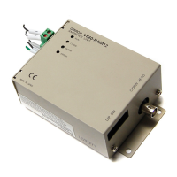
Amplifier Unit V640-HAM12 16
ASCII Code Table 132
B
Byte Write 84
C
Change the data segment area 49
Change the response time-out time 52
Changing the Position of the Mode Switch on the
Bottom of the Unit
44
Characteristic Data depending on Conditions of Use
105
CIDRW Controller 22, 27
CIDRW Controller V700-L21 15
CIDRW Head 24
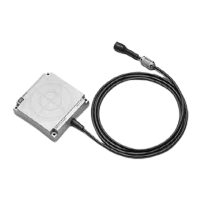
CIDRW Head V640-HS61 17
CIDRW Systems that Conform to SEMI Standards
(SEMI E99, E5, E4)
13
Coaxial Mounting 106, 107, 112, 113
Command 79
Command/Response Format 77
Communications Distance Characteristics vs. Ambi-
ent Noise
124
Communications Test 61
Communications Time 121
Component Names and Functions 15
Connections and Wiring 27
Connector for connecting a CIDRW Head 30
Controller Indicators 88
D
Data Reading and Writing 24
Data Segment Area 125
F
Features 13
Flowchart for Getting Started 19
For Coaxial Installation
118
For Face-to-Face Installation
119
For Parallel Installation
119
From Installation to Trial Operation 95
From Trial Operation to Communications 97
H
Host Connection Port 38
I
ID Tag ´ CIDRW System Communications Test 62
IEC (International Electrotechnical Commission)
Standard (IEC60529
1989-11) 133
Influence of Background Metal on ID Tag 25
Influence of Background Metals (Reference Only)
120
Influence of Noise 25
Installation 22
L
Link Unit 26, 37
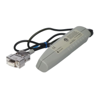
Link unit V700-L11 18
List of Error Messages 88, 94
M
Maps of Communications Areas (Reference Only)
106
Message Specifications 66
Mounting 25
Multi-connection port 41
Mutual Interference Distances (Reference Only)
118
N
NAK 86
Noise measurement 86
Normal Operation Mode 89
O
Operation Check Flowchart 89, 95
Operation Model 127
P
Parallel Mounting 108, 109, 114, 115
Positional Relationship between the CIDRW Head
and the ID Tag
24
Power Supply 37
Power Supply and Grounding Wires 27, 30
Protective Construction 133
Protocol Specifications 128
R
READ 80
Regular Inspection 126
RESET 86
Return to the Normal Operation mode 54
RS-232C Port 32
RS-485 Port 35