18
SECTION 1
Component Names and Functions
CIDRW System
User’s Manual
SECTION 1
Product Outline
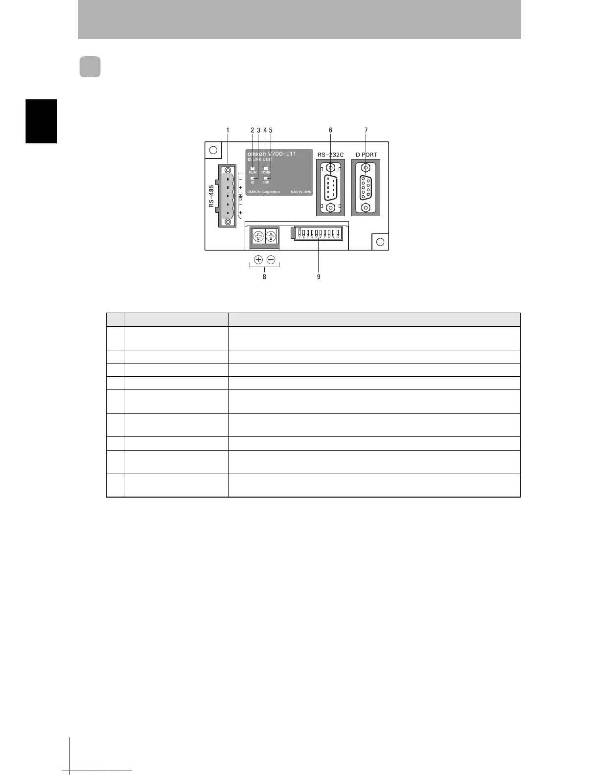
Link Unit V700-L11
No. Name Function
1 Multi-connection port
(RS-485)
This is the port that connects to the Amplifier Units when multiple CIDRW Heads are
connected to a CIDRW Controller. The GR (frame ground) terminal is also at this port.
2 RUN indicator (green) Turns ON while the Link Unit is in normal operation.
3 ID indicator (green) Not used
4 COMM indicator (green) Turns ON during data communications with the host device.
5 ERR indicator (red) Turns ON when an error occurs during data communications with the host device or
head.
6 Host device connection port
(RS-232C)
This is a port for connecting to the CIDRW Controller via an RS-232C interface. A dust
cover is fitted on shipment from the factory. Remove this cover before using the port.
7 ID connection port Not used
8 24 V power supply terminals
(inside the cover)
Connect to the 24 VDC power supply.
9 Setting DIP switches
(inside the cover)
Used to set the equipment number, the communications conditions, and the RS-485 ter-
minal resistance.