28
SECTION 2
Connections and Wiring
CIDRW System
User’s Manual
SECTION 2
Installation and Connections/Wiring
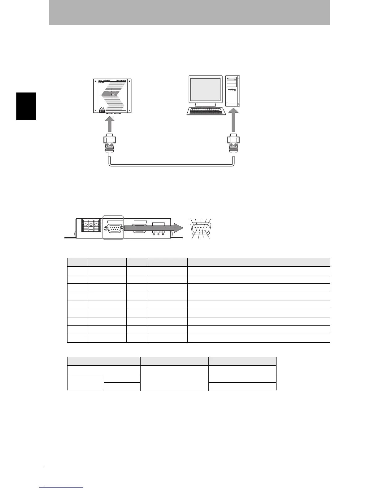
■ SECS port
The method for wiring for communications with a host device via the SECS port is explained here.
• Connector
The SECS port on the Controller is a D-SUB 9-pin connector. The pin arrangement is shown below.
Recommended model
Pin No. Signal name Symbol Signal direction Remarks
1 — NC — Not connected
2 Receive data RD Input
3 Send data SD Output
4 — — Output Always OFF
5 Signal ground SG —
6 — — Input Use in the open status.
7 Request send RS Input Always ON during normal operation
8 — NC — Not connected
9 — NC — Not connected
Manufacturer Model
Cable Hitachi Cable CO-MA-VV-SB 5PX28AWG
Connector Socket OMRON XM2D-0901
Hood XM2S-0913
CIDRW Controller
Host
To the RS-232 port
To the SECS port
RS-232C
SECS ID
MAINTENANNCE
12 3
6789
45
The connector rim has electrical continuity with the
GR (frame ground) in the 24 VDC power supply ter-
minals.