50
SECTION 3
Set the Communications Conditions for the CIDRW Controller
CIDRW System
User’s Manual
SECTION 3
Preparing for Communications
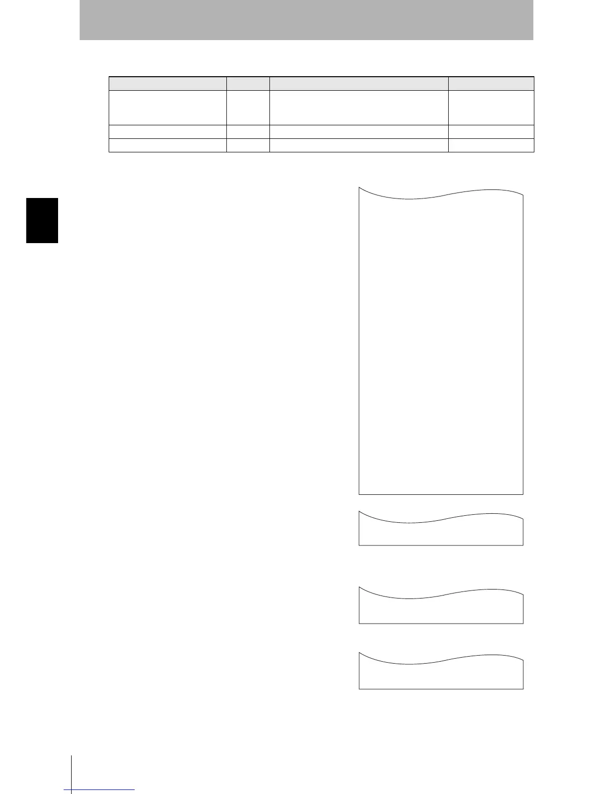
1. The form of the input from the host device is shown in the
figure to the right.
When the first parameter is specified, the ALARMS indicator flashes.
2. Confirm the parameter change.
The input parameter is checked and written.
When writing is completed, a message indicating the result is displayed.
The ALARMS indicator lights.
If writing is completed with an error, the parameters are not updated.
The figure in square brackets [ ] indicates the line number where the
error was first detected. If a parity error is detected in the received char-
acters, this figure is [0].
Check the sent data based on this information.
Tag Name List
Parameter Tag name Setting range Default setting
Number of bytes in the carrier ID T_CIDLEN 8, 16
The setting must maintain the following relationship
(CIDOF + CIDLN) ≤ T_CIDLEN
16
Segment name T_SEGN "S01" to "S99" "S01" to "S28"
Number of bytes in a segment T_SEGL 8 (fixed) 8
T_CIDLEN=16
T_SEGN=S01
T_SEGL=8
T_SEGN=S02
T_SEGL=8
T_SEGN=S03
T_SEGL=8
T_SEGN=S04
T_SEGL=8
T_SEGN=S05
T_SEGL=8
T_SEGN=S06
T_SEGL=8
T_SEGN=S07
T_SEGL=8
T_SEGN=S08
T_SEGL=8
T_SEGN=S09
T_SEGL=8
T_SEGN=S10
T_SEGL=8
T_SEGN=S11
T_SEGL=8
T_SEGN=S12
T_SEGL=8
T_SEGN=S13
T_SEGL=8
T_SEGN=S14
T_SEGL=8
T_SEGN=S15
T_SEGL=8
_
::END
_
SETUP_COMPLETE
_
SETUP_FAILED [2]_
When writing is completed without error
When writing is completed with an error