EXHAUST
SYSTEM
The condition of the exhaust system is extremely
critical on
RV
generator sets because of the possibil-
ity of exhaust gases entering the coach.
The exhaust system must be serviced immediately
if
inspection
reveals leaking joints or connections, loose fasteners, or broken or
damaged components.
Always replace worn components with new original
equipment replacement parts.
Do
not attempt to
repair a broken exhaust pipe or manifold by welding
and do not replace worn out components with parts
that do not meet factory specifications.
Exhaust presents the hazard of
k%!@!&l
severe personal injury or death.
Modifying the exhaust system mlght allow poisonous
exhaust gases
to
enter the coach. Use only original
equlpment replacement parts when servlclng the
exhaust system. Unauthorized modiflcaflons willalso
void the warranty and cancel the
UL
Llst/ng/CSA
Cerflflcatlon. Llabl//ty for injury or damages due to
unauthorlzed modiilcations becomes the responsi-
billfy of the person making the change.
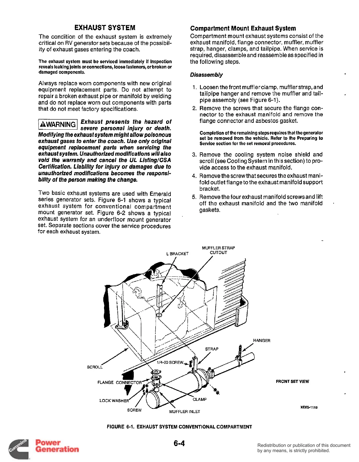
Two basic exhaust systems are used with Emerald
series generator sets. Figure
6-1
shows a typical
exhaust system for conventional compartment
mount generator set. Figure
6-2
shows a typical
exhaust system for an underfloor mount generator
set. Separate sections cover the service procedures
for each exhaust system.
Compartment
Mount
Exhaust
System
Compartment mount exhaust systems consist of the
exhaust manifold, flange connector, muffler, muffler
strap, hanger, clamps, and tailpipe. When service is
required, disassembleand reassemble as specified in
the following steps.
Disassembly
1.
2.
3.
4.
5.
Loosen the front mufflerclamp, muffler strap, and
tailpipe hanger and remove the muffler and tail-
pipe assembly (see Figure
6-1).
Remove the screws that secure the flange con-
nector to the exhaust manifold and remove the
flange connector and asbestos gasket.
Completion
of
the remaining steps requires that thegenerator
set
be
removed from the vehicle. Refer
to
the Preparing to
Service section lor the set removal procedures.
Remove the cooling system noise shield and
scroll (see Cooling System in this section) to pro-
vide access to the exhaust manifold.
Remove the screw that secures the exhaust mani-
fold outlet flange to the exhaust manifold support
bracket.
Remove the four exhaust manifold screwsand lift
off the exhaust manifold and the two manifold
gaskets.
a
MUFFLER
STRAP
L
BRACKET
CUTOUT
v,
STRAP
PJ
SCROl
F
CLAMP
IGER
FRONT
SET
VIEW
XEXS-1118
FIGURE
6-1.
EXHAUST SYSTEM CONVENTIONAL COMPARTMENT
6-4
Redistribution or publication of this document
by any means, is strictly prohibited.
Redistribution or publication of this document
by any means, is strictly prohibited.
 Loading...


