the specified amount.
Do
not hammer
the
new
pin
into place or it will be damaged. The camshaft center
pin cannot be pulled outward nor removed without
damage.
If
the
center
pin
extends
out
too far,
the
cup
will
not hold the flyballs.
TIMING
GEARS
AND CAMSHAFT
If replacement of either the crankshaft gear or the
camshaft gear becomes necessary, it is recom-
mended that both gears be replaced.
To remove the crankshaft gear, first remove the snap
ring and retainer washer; then attach the gear pulling
ring using two
No.
10-32
screws (Figure
9-15).
Tighten the screws alternately until both are tight.
Attach a gear puller to the puller ring and remove the
gear.
The camshaft and gear are removed
as
an assembly.
Before removing the camshaft and gear assembly,
remove the cylinder head and valve assemblies. Then
remove the operating plunger for the breaker points
and tappets.
CRANKSHAFT
THESE
MARKS
MUST
ALIGN
WHEN
INSTALL-
ING
TIMING
GEARS.
VT-1029
FIGURE 9-15.
TIMING
GEAR
REMOVAL
AND
INSTALLATION
.
Each timing gear is stamped with
“0”
near the edge.
The gearteeth must mesh
so
that these marks exactly
coincide when the gears are installed in the engine.
When installing the camshaft gear and shaft assem-
bly, be sure that the thrust washer
is
properly
in
place
behind thecamshaft gear.Then install thecrankshaft
retaining washer and lock ring.
LUBRICATION SYSTEM
All generator set engines use an oil pump to provide a
constant flow of oil to theengine parts.Theoil supply
collects
in
the
oil
base where
it
is
picked up by the oil
pump pick-up cup.
A
by-pass valve is used to control
oil pressure. Drain the
oil
before removing the oil
base and always usea new gasket when replacing the
oil base.
Oil
Pump
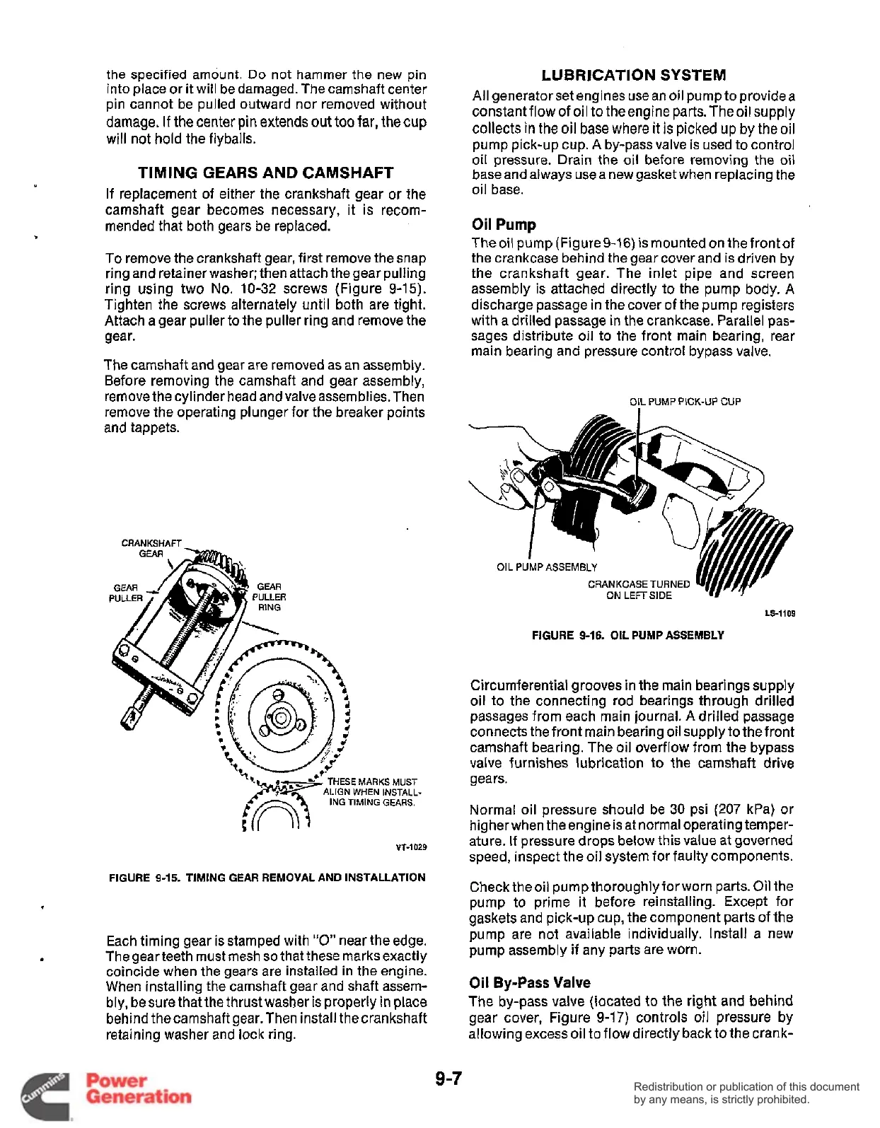
Theoil pump (Figure9-16) ismounted on the frontof
the crankcase behind the gear cover and is driven by
the crankshaft gear. The inlet pipe and screen
assembly is attached directly to the pump body. A
discharge passage in the cover of the pump registers
with a drilled passage in the crankcase. Parallel pas-
sages distribute oil to the front main bearing, rear
main bearing and pressure control bypass valve.
OIL
PUMP
PICK-UP
CUP
CRANKCASE
TURNED
ON
LEFT
SIDE
LS-1109
FIGURE
9-16.
OIL
PUMP
ASSEMBLY
Circumferential grooves in the main bearings supply
oil to the connecting rod bearings through drilled
passages from each main journal. A drilled passage
connects the front main bearing oil supply to the front
camshaft bearing. The oil overflow from the bypass
valve furnishes lubrication to the camshaft drive
gears.
Normal oil pressure should be
30
psi
(207
kPa) or
higher when the engine is at normal operating temper-
ature. If pressure drops below this value at governed
speed, inspect the oil system for faulty components.
Check theoil pump thoroughlyforworn parts.
Oil
the
pump to prime it before reinstalling. Except for
gaskets and pick-up cup, the component parts of the
pump are not available individually. Install a new
pump assembly if any parts are worn.
Oil
By-Pass
Valve
The by-pass valve (located to the right and behind
gear cover, Figure
9-17)
controls
oil
pressure by
allowing excess oil to flow directly back to the crank-
9-7
Redistribution or publication of this document
by any means, is strictly prohibited.
Redistribution or publication of this document
by any means, is strictly prohibited.
 Loading...


