,
4.61
IN
(117 mm)
If
theTI-T3 lead
is
grounded, the sourceofthe ground
could be either the stator windings or the transformer
primary windings. To isolate, disconnect the trans-
former primary leads from the stator leads
(T2
from
H2
andT4from H4).Touchthe test prod toTl-T3,
H2,
and
H4 to identify the grounded component. Replace a
grounded stator or transformer with a new part.
STATOR TRANS
T1 to H1
T3 to H3
61 to
62
X1 toX6
STATOR ONLY
T1 toT2
T3 to T4
TRANS ONLY
H4 to
H3
H2 to H1
Open orshorted
Windings:
To
test for opens, discon-
nect the transformer and stator leads as specified in
the Ground Test section. Set the ohmmeter for the
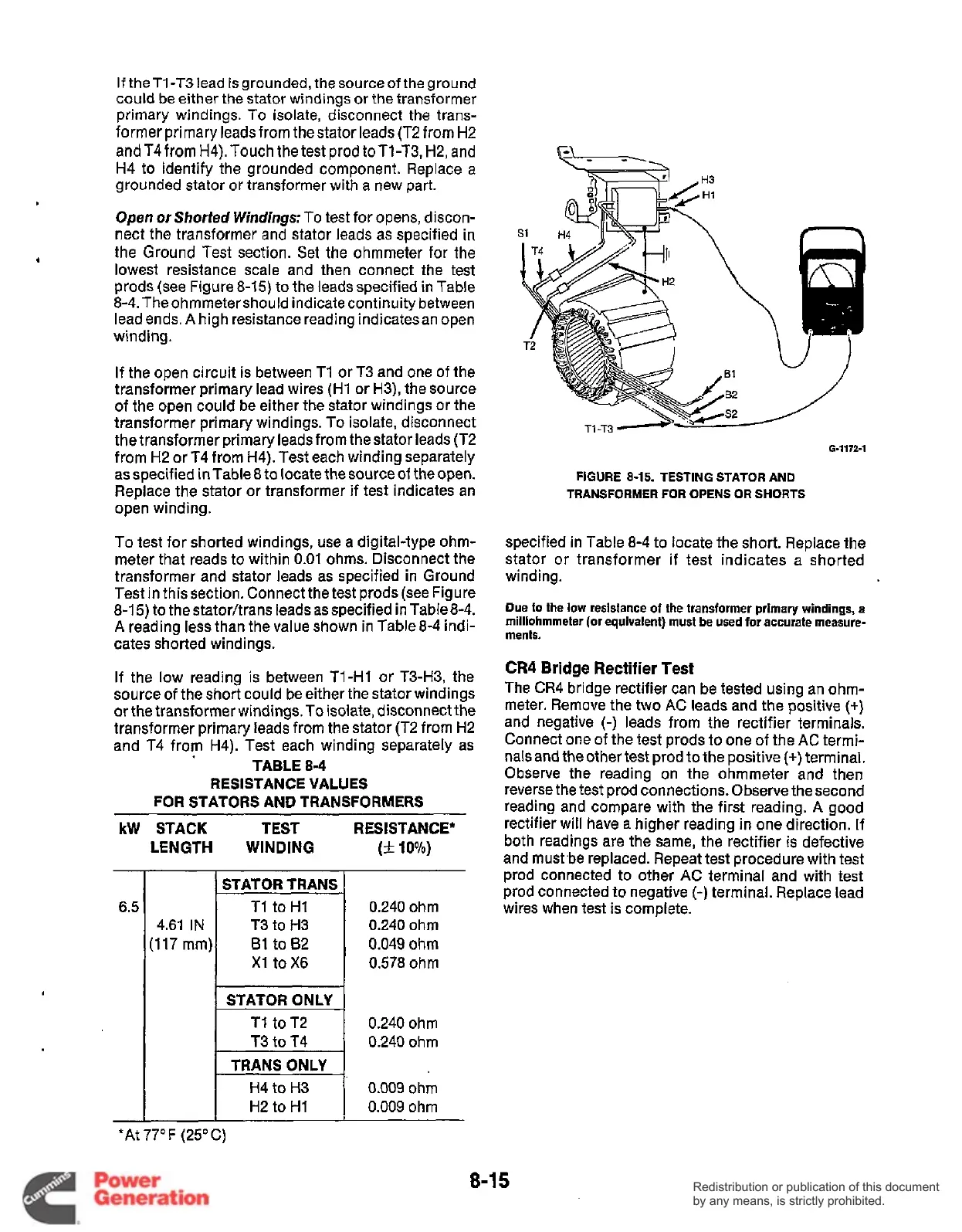
lowest resistance scale and then connect the test
prods (see Figure 8-15) to the leads specified in Table
8-4. The ohmmetershould indicate continuity between
lead ends.
A
high resistance reading indicatesan open
winding.
If the open circuit is between T1
Or
T3 and one
of
the
transformer primary lead wires (H1 or H3), the source
of the open could be either the stator windings or the
transformer primary windings. To isolate, disconnect
the transformer primary leads from the stator leads (T2
from H2 or T4 from H4). Test each winding separately
as specified in Table
8
to
locate the source of the open.
Replace the stator or transformer if test indicates an
open winding.
To test for shorted windings, use a digital-type ohm-
meter that reads to within 0.01 ohms. Disconnect the
transformer and stator leads as specified in Ground
Test in thissection. Connect the test prods (see Figure
8-15) to the stator/trans leads as specified in Table8-4.
A
reading less than the value shown in Table 8-4 indi-
cates shorted windings.
If the low reading is between Tl-HI or T3-H3, the
source
of
the short could be either the stator windings
or the transformer windings. To isolate, disconnect the
transformer primary leads from the stator (T2 from H2
and
T4
from H4). Test each winding separately as
RESISTANCE VALUES
FOR STATORS AND TRANSFORMERS
kW STACK TEST RESISTANCE*
TABLE
8-4
LENGTH WINDING
(*
10%)
-
6.5
-
0.240 ohm
0.240
ohm
0.049
ohm
0.578 ohm
0.240 ohm
0.240 ohm
0.009
ohm
0.009
ohm
6-1172-1
FIGURE
8-15.
TESTING STATOR AND
TRANSFORMER FOR
OPENS
OR
SHORTS
specified in Table 8-4 to locate the short. Replace the
stator or transformer if test indicates a shorted
winding.
Due
to
the low resistance
of
the
transformer primary windings, a
milliohmmeter
(or
equivalent) must be used for accurate measure-
ments.
CR4
Bridge Rectifier Test
The CR4 bridge rectifier can be tested using an ohm-
meter. Remove the two
AC
leads and the positive
(+)
and negative
(-)
leads from the rectifier terminals.
Connect one of the test prods to one of the
AC
termi-
nals and theother test prod
to
the positive (+)terminal.
Observe the reading on the ohmmeter and then
reverse the test prod connections. Observe the second
reading and compare with the first reading.
A
good
rectifier will have a higher reading in one direction. If
both readings are the same, the rectifier is defective
and must.be replaced. Repeat test procedure with test
prod connected to other
AC
terminal and with test
prod connected to negative
(-)
terminal. Replace lead
wires when test is complete.
*At 77°F (25°C)
8-1
5
Redistribution or publication of this document
by any means, is strictly prohibited.
Redistribution or publication of this document
by any means, is strictly prohibited.