Nikki
Carburetor
-
Throttle
Stop,
Fuel
Mixture Adjustment,
and
Float
Setting
Throtlle
Stop
(/d/e Adjust):
Connect a frequency meter
to generator set. Start the generator set and operate at
no-load. Turn in the throttle stop screw (idle adjust) to
contact the throttle levertab. While adjusting screw, pull
the governor linkage toward the engine and monitor the
frequency meter. Adjust the screw to obtain the follow-
ing setting:
0
60
Hz Model
-
55
f
1
hertz/1650
*
30 r/min.
50
Hz Model
-
45
f
1 hertz/1350
k
30 r/min.
Release governor linkage and check unit frequency and
voltage. Refer to Governor Adjustments in section
6
of
service manual. Perform necessary adjustments to
achieve proper setting.
Mixture
Screw
Adjustments:
If generator set voltage
and frequency (rimin) cannot be satisfactory adjusted,
and the generator set operation
is
erratic, stop the
generator set and review the following idle and main
fuel mixture screw adjustments.
A.
0
0
0
B.
0
0
0
Idle mixture screw adjustment:
Carefully remove screw adjustment limiter cap.
Using a screwdriver, carefully turn the idle mix-
ture screw inward until lightly seated, and then
back out exactly one
(1)
full turn.
Carefully replace screw adjustment limiter cap
over screw head, with limiter lever located at the
LOW
altitude position.
Takecarenottochangesettingand confirm that limiter cap
is
fully
seated
over
screw head.
Main mixture screw adjustment:
Carefully remove screw adjustment limiter cap.
Turn the main mixture screw inward until lightly
seated, and then back out exactly one and one-
quarter
(1-1
/4)
full turns out.
Carefully replace screw adjustment limiter cap
over screw head, with limiter lever located at the
LOW
altitude position.
Take care not
to
changesetting and confirm that limiter cap
is
fully
seated
over
screw head.
Review Governor Adjustments
in
section
6.
Add and
remove a full load several times to make certain the
generator set does not bog down or hunt. Stop genera-
tor set, remove meter(s) and
tools,
and close
up
genera-
tor set compartment.
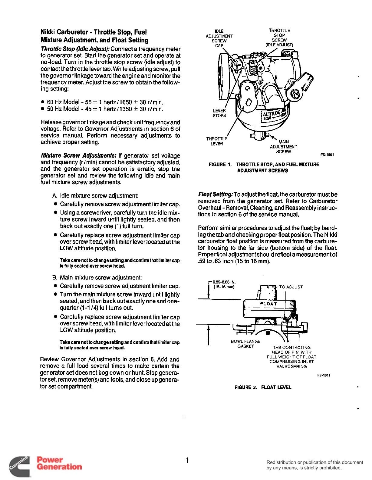
IDLE
THROTTLE
ADJUSTMENT STOP
SCREW
SCREW
CAP
(IDLE
ADJUSI)
ADJUSTMENT
SCREW
LEVER
FIGURE
1.
THROTTLE
STOP,
AND FUEL MIXTURE
ADJUSTMENT SCREWS
FS-1691
F/oatSeffing:To
adjustthe float, the carburetor must be
removed from the generator set. Refer to Carburetor
Overhaul
-
Removal, Cleaning, and Reassembly instruc-
tions in section 6 of the service manual.
Perform similar procedures to adjust the float; by bend-
ing the tab and checking proper float position. The Nikki
carburetor float position is measured from the carbure-
tor housing to the far side (bottom side) of the float.
Proper float adjustment should reflecta measurement of
.59
to .63 inch (15 to
16
mm).
059-0.63
IN.
r
(15-16
rnrn)
luw
TOADJUST
t
t
BOWL
FLANGE
GASKET TAB CONTACTING
HEAD OF PIN. WITH
FULL WEIGHT OF FLOAT
COMPRESSING INLET
VALVE SPRING
I
FS-1611
FIGURE 2. FLOATLEVEL
1
Redistribution or publication of this document
by any means, is strictly prohibited.
Redistribution or publication of this document
by any means, is strictly prohibited.
 Loading...


