REMOTE PANELS
STANDARD
DELUXE
p
E3
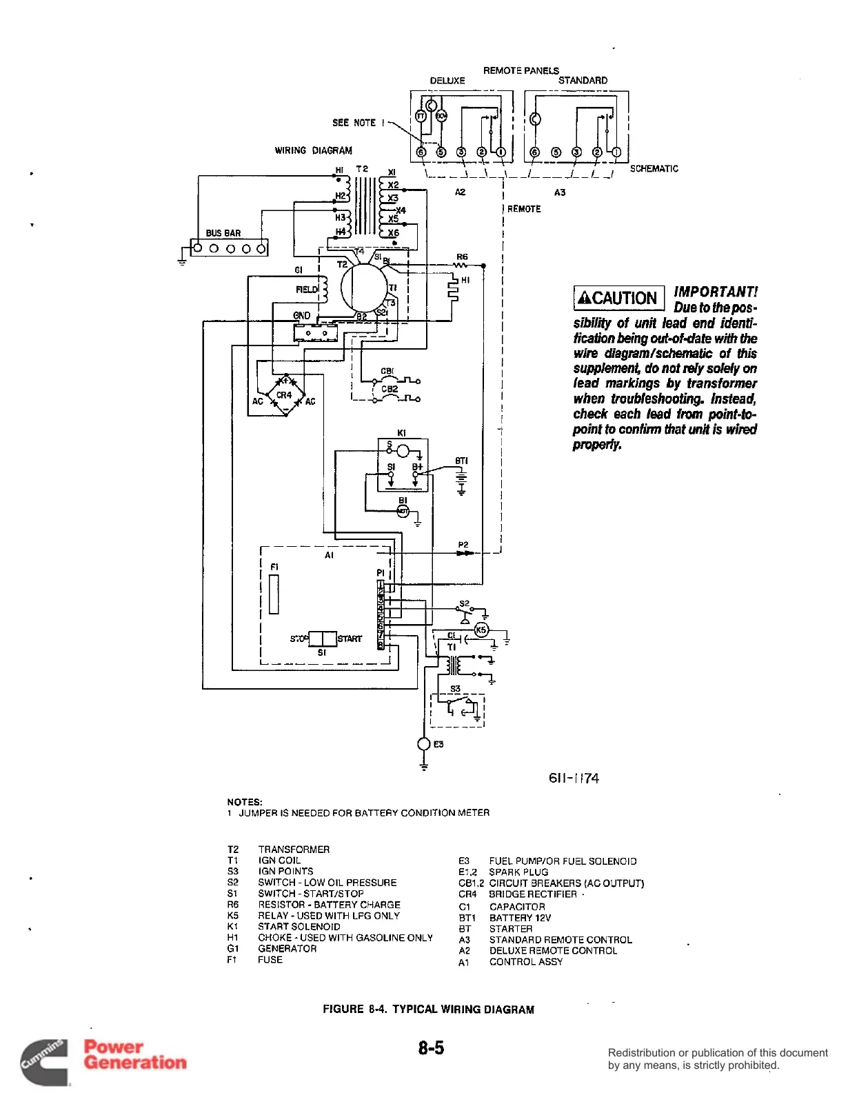
NOTES:
1
JUMPER IS NEEDED FOR BATTERY CONDITION METER
A3
I
I
REMOTE
I
I
I
I
I
I
I
I
I
I
I
I
I
I
I
I
I
I
1
I
I
I
I
I
I
I
I
I
I
-1
IMPORTANT!
Due to thepos-
sibility
of
unit lead end identi-
fication being out-ofdate
with
the
wire diagnm/schematic of
this
supplemnb do nof dy solely on
lead
markings by transformer
when troubleshoofing. Instead,
check
each lead
from
pint-io-
point to confinn that
unit
is
wired
PrOperY.
T2
Tl
s3
s2
s1
R6
K5
K1
H1
G1
F1
61
I-
I
174
TRANSFORMER
IGN COIL E3 FUEL PUMP/OR FUEL SOLENOID
IGN POINTS El
2
SPARK PLUG
SWITCH -LOW OIL PRESSURE
RESISTOR -BATTERY CHARGE C1 CAPACITOR
RELAY
-
USED WITH LPG ONLY BT1 BATTERY 12V
START SOLENOID
BT STARTER
GENERATOR
A2 DELUXE REMOTE CONTROL
FUSE
A1 CONTROL ASSY
CB1.2 CIRCUIT BREAKERS (AC OUTPUT)
SWITCH
-
START/STOP CR4 BRIDGE RECTIFIER
-
CHOKE
-
USED WITH GASOLINE ONLY A3 STANDARD REMOTE CONTROL
FIGURE
8-4.
TYPICAL
WIRING
DIAGRAM
8-5
Redistribution or publication of this document
by any means, is strictly prohibited.
Redistribution or publication of this document
by any means, is strictly prohibited.