contact the valve face evenly at all points. The line
of
contact should be at the center
of
the valve face.
Valve
Guide
Replacement
Worn valve stem guides can be replaced from inside
the valve chamber (aseal is provided behind the intake
valve guides only). The smaller diameter of the tapered
valve guides must face toward the valve head. Tappets
are also replaceable from the valve chamber after first
removing the valve assemblies.
Removal:
Before removing valve guides, use an elect-
ric drill with a wire brush to remove carbon and other
foreign material from top surface
of
guides. Failure to
perform this operation may result in damage to the
guide bores. Drive the guides out with a hammer and
valve guide driver.
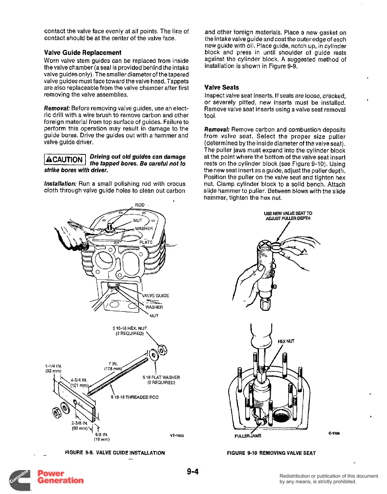
and other foreign materials. Place a new gasket on
the intake valve guide and coat the outer edge of each
new guide with oil. Place guide, notch up, in cylinder
block and press in until shoulder of guide rests
against the cylinder block.
A
suggested method of
installation is shown in Figure
9-9.
Valve Seats
Inspect valve seat inserts.
If
seats are loose, cracked,
or severely pitted, new inserts must be installed.
Remove valve seat inserts using a valve seat removal
tool.
Removal;
Remove carbon and combustion deposits
from valve seat. Select the proper size puller
(determined by the inside diameter of the valve seat).
The puller jaws must expand into the cylinder block
at the point where the bottom of the valve seat insert
rests on the cylinder block (see Figure
9-10).
Using
the new seat insert asa guide, adjust the pullerdepth.
Position the puller on the valve seat and tighten hex
nut. Clamp cylinder block to a solid bench. Attach
slide hammer to puller. Between blows with the slide
hammer, tighten the hex nut.
Driving
out
old guides can damage
liiBB4I
the tapped bores. Be careful not to
strike bores
wlfh
driver.
Insfallation:
Run a small polishing rod with crocus
cloth through valve guide holes to clean out carbon
ROD
.
USE
NEW
VALVE
SEAT
TO
ADJUST
PULER
DEPTH
5
16-18
HEX.
NUT
(2
REQUIRED)
\
1-It4
IN.
(32
mm)
5
16
FLAT
WASHER
(2
REQUIRED)
5
16-18THREADED
ROD
.-
FIGURE 9-9. VALVE GUIDE INSTALLATION
-
UT-1023
WUERLWS
FIGURE
9-10
REMOVING VALVE SEAT
GllU
9-4
Redistribution or publication of this document
by any means, is strictly prohibited.
Redistribution or publication of this document
by any means, is strictly prohibited.
 Loading...


