Section
9
-
Engine
Block
Assembly
GENERAL
The engine block assembly includes the pistons and
connecting rods, crankshaft, camshaft, valves and
lif-
ters, cylinder heads, lubrication system, timing gears,
governor mechanism, bearings, and cylinder block.
Performing any major service on the block assembly
will require that thegeneratorset be removed from the
coach (see Set Removal in Section
5).
In addition, to
gain complete access to the block assembly, the con-
trol, generator, and all primary engine systems must
also be removed. Refer to the previous sectionsforthe
disassembly and removal procedures.
OIL
FILTER
AND
ADAPTER
Open the oil drain valve and drain the crankcase oil.
Remove the filter (see Figure
9-1)
by turning counter-
clockwise with a filter wrench. The low oil pressure
cut-off switch is installed in athreaded hole in the filter
adapter and may be removed if. required. Loosen the
two capscrews that secure the adapter to the engine
block and remove the adapter and gasket.
Assembly is the reverse of disassembly. Use a new
adapter gasket and install
so
the two small oil holes are
aligned with the oil holes in the block. Gasket should
be installed dry. Coat the threads of each capscrew
with non-hardening sealer and tighten to recom-
mended torque.
LOW
OIL
h
LS-1111
FIGURE
9-1.
OIL
FILTER AND ADAPTER
-
CYLINDER HEADS
Remove the cylinder heads for cleaning when poor
engine performance is noticed. Use the following
procedures
to
service.
1. Use a
1/2
inch socket wrench to remove the
cylinder head bolts or stud nuts and lift off the
head.
2.
3.
4.
5.
Warpage can occur if
the
heads
ACAUTION
are removed while hot. Waif until
engine has cooled before removing heads.
After removing heads, clean out all carbon depos-
its. Be careful not
to
damage the outer sealing
edges where gaskets fit. The heads are made of
aluminum and can bedarnaged by careless handling.
Use new head gaskets and clean both the heads
and the cylinder block thoroughly where the head
gaskets rest.
Place a head gasket on the cylinder head and align
the stud holes in the gasket with the stud holes in
the cylinder head. While holding the gasket
against the cylinder head, carefully install the
cylinder head on the engine.
Do
not attempt to
slide the gasket over the studs without the cylinder
head behind
it
or the gasket may tear.
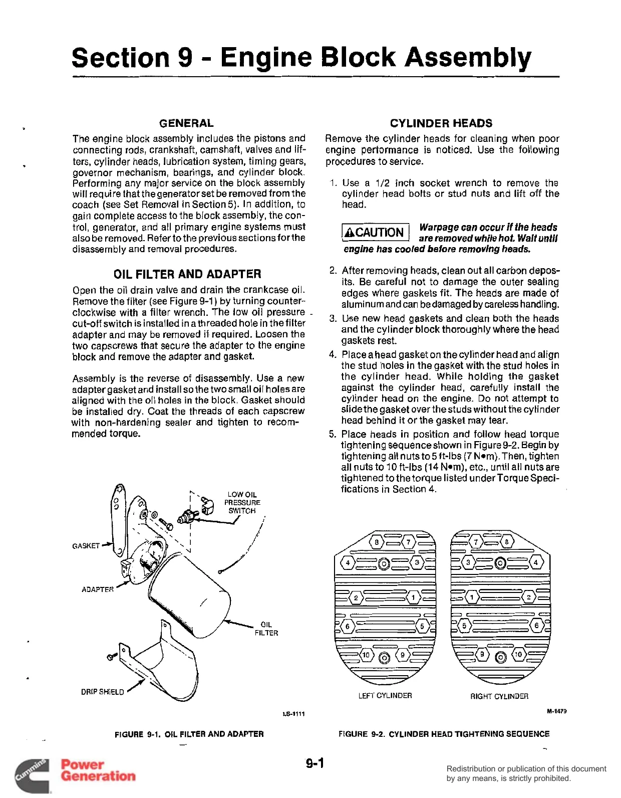
Place heads in position and follow head torque
tightening sequenceshown in Figure
9-2.
Begin by
tightening all nuts to5ft-lbs
(7
N*m).Then, tighten
all nuts to 10 ft-lbs (14 Nom), etc., until all nuts are
tightened to the torque listed under TorqueSpeci-
fications in Section 4.
LEFTCYLINDER
RIGHT
CYLINDER
M-1479
FIGURE
9-2.
CYLINDER HEAD TIGHTENING SEQUENCE
-
'9-1
Redistribution or publication of this document
by any means, is strictly prohibited.
Redistribution or publication of this document
by any means, is strictly prohibited.