Refer to Table 6-3 to determine the number of
degrees element cover must be rotated (clock-
wise) from reference position. Marks on choke
housing are spaced at
5"
intervals.
Rotate element cover asspecified and then tighten
cover mounting screws.
Move choke lever back and forth to check for
smooth operation. Lever should return automati-
cally to the free position when released from the
open position without sticking or binding.
Install plastic choke cover and tighten center
mounting nut.
ChokeReplacement:
If
the choke fails to open, remove
the protective plastic cover and check to see
if
the
heating element is working. The heating element cover
should become hot after a few minutes of operation. If
the element cover does not get hot, start the set and
then use an AC voltmeter to check for voltage (approx-
imately 20 VAC) at the element cover terminals.
If
voltage is not present, check for opens or shorts in the
control wiring.
If
the voltage is present at the heating element cover
terminals, stop the set and remove the heating element
cover. Inspect the heating element and replace
if
burned out or broken.
Also
inspect the bi-metal spiral
strip and replace if damaged, deteriorated, or dragging
in the housing.
When installing a new bi-metal strip, maintain the orig-
inal direction of spiral (see Figure 6-20). The outer tab
must point in a clockwise direction. Make sure the coil
sets squarely in the housing and the inner end of the
coil engages the slot in the choke shaft. When instal-
ling the element cover, make sure the slotted tang on
the cover engages the bi-metal strip.
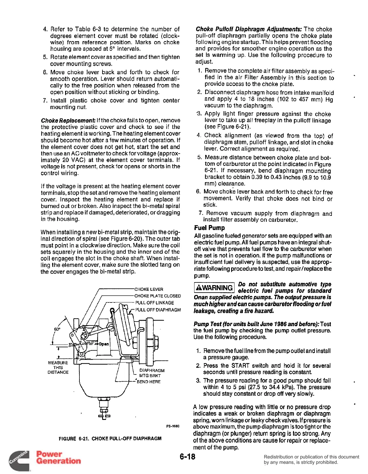
CHOKE LEVER
/-CHOKE
PLATE
CLOSED
.GM
L=J-
ENDHERE
FS-1603
FIGURE
6-21.
CHOKE
PULL-OFF DIAPHRAGM
Choke Pulloff Diaphragm Adjustments:
The choke
pull-off diaphragm partially opens the choke plate
following engine startup. This helps prevent flooding
and provides for smoother engine operation as the
set is warming up. Use the following procedure to
adjust.
1.
2.
3.
4.
Remove the complete air filter assembly as speci-
fied in the air Filter Assembly in this section to
provide access to the choke plate.
Disconnect diaphragm hose from intake manifold
and apply
4
to
18
inches (102 to 457 mm) Hg
vacuum to the diaphragm.
Apply light finger pressure against the choke
lever to take up all freeplay in the pulloff linkage
(see Figure 6-21).
Check alignment (as viewed from the top) of
diaphragm stem, pulloff linkage, and slot in choke
lever. Correct alignment as required.
5.
Measure distance between choke plate and bot-
tom of carburetor at the point indicated in Figure
6-21. If necessary, bend diaphragm mounting
bracket to obtain 0.39 to 0.43 inches (9.9 to 10.9
mm) clearance.
6. Move choke lever back and forth to check for free
movement. Verify that choke does not bind or
stick.
7.
Remove vacuum supply from diaphragm and
install filter assembly on carburetor.
Fuel
Pump
All
gasoline fueled generator sets are equipped with an
electric fuel pump.
All
fuel pumps have an integral shut-
off
valve that prevents fuel flow to the carburetor when
the set is not in operation.
If
the pump malfunctions or
insufficient fuel delivery is suspected, use the approp-
riate following procedure
to
test, and repairheplace the
Pump.
Do
not substitute automotive type
[BWARNINGI
electric fuel pumps for standard
Onan supplied electric pumps. The output pressure is
much higher and can cause carburetor flooding
or
fuel
leakage, creating a fire hazard.
Pump Test (for units built June
1986
and before):
Test
the fuel pump by checking the pump outlet pressure.
Use the following procedure.
1. Remove the fuel line from the pump outlet and install
a pressure gauge.
2.
Press the START switch and
hold it for several
seconds until pressure reading is constant.
3.
The pressure reading for a good pump should fall
within 4 to
5
psi
(27.5
to 34.4 kPa). The pressure
should stay constant or drop
off
very slowly.
A
low
pressure reading with little or no pressure drop
indicates a weak or broken diaphragm or diaphragm
spring, worn linkage or leakycheckvalves.
If
pressure is
above maximum, the pump diaphragm is too tight or the
diaphragm (or plunger) return spring
is
too
strong.
Any
of the above conditions are cause for repair or replace-
ment of the pump.
6-1
8
Redistribution or publication of this document
by any means, is strictly prohibited.
Redistribution or publication of this document
by any means, is strictly prohibited.