GENERATOR
SERVICE
This section covers generator disassembly and assem-
bly procedures. Referto Figures8-1 and8-2 tolocateand
identify the various generator components described in
each su b-section.
Generator
Disassembly
Use the following procedures to disassemble the
generator:
1. Drain the engine oil while the generator set is still
mounted in the vehicle.
2. Remove the generator set from the vehicle and place
it
on
a sturdy work bench. Refer to Set Removal in
Section
5
for the recommended set removal
procedures.
3.
Remove the flywheel guard (from scroll opening)
and the noise shield.
4.
The carburetor and intake manifold must be
removed to provide clearance for lifting the genera-
tor stator assembly. Disconect the choke heater lead
wires, throttle linkage, fuel line, crankcase breather
hose, and preheater tube. Remove the intake mani-
fold as an assembly. Refer to Fuel System in Section
6 for detailed removal procedures.
5.
Disconnect the lead wires from the charge resistor
(quick-disconnect type connections), the low oil
pressure cutoff switch, and the
B+
terminal on the
ignition coil.
6.
Remove the brush block cover and disconnect the
Bt
(outboard) and
B-
(inboard) lead wires from the
brush block terminals.
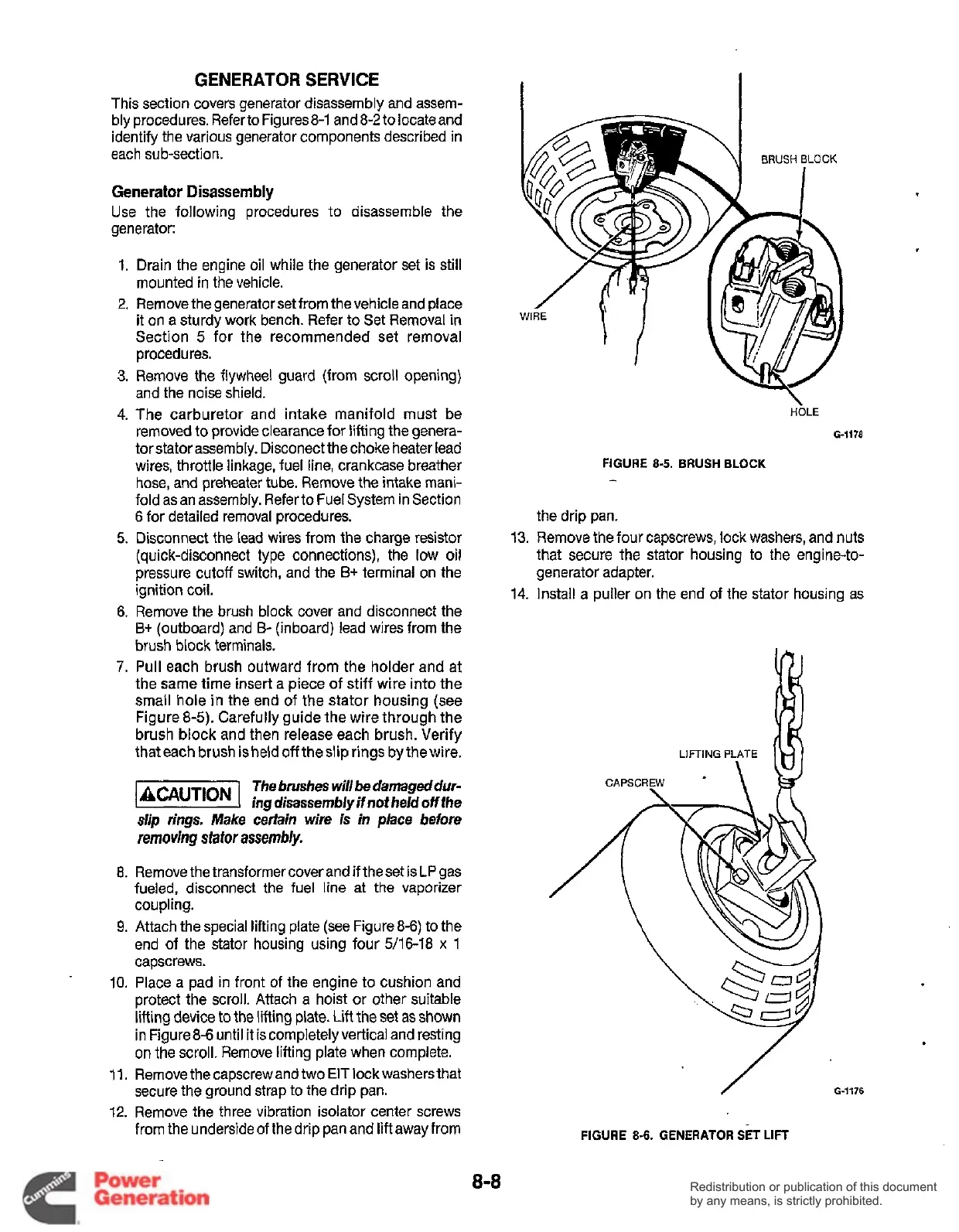
7.
Pull each brush outward from the holder and at
the same time insert a piece of stiff wire into the
small hole in the end
of
the stator housing (see
Figure 8-5). Carefully guide the wire through the
brush block and then release each brush. Verify
thateach brush is held
off
theslip rings by thewire.
BRUSH
BLOCK
HOLE
G-1178
FIGURE
8-5.
BRUSH
BLOCK
-
the drip pan.
13.
Remove the four capscrews, lock washers, and nuts
that secure the stator housing to the engine-to-
generator adapter.
14. Install a puller on the end of the stator housing as
The brushes will
be
damageddur-
incrdisassemblvif notheld offfhe
slip
rings.
Make
c&dn wire
is
in place before
removing
sfafor
assembly.
8.
Remove the transformer coverand
if
theset is
LP
gas
fueled, disconnect the fuel line at the vaporizer
coupling.
9.
Attach the special lifting plate (see Figure 8-6)
to
the
end of the stator housing using four 5/16-18
x
1
10.
11.
12.
capscrews.
Place a pad in front
of
the engine to cushion and
protect the scroll. Attach a hoist or other suitable
lifting device
to
the lifting plate.
Lift
the set as shown
in Figure84 until it is completelyvertical and resting
on the scroll. Remove lifting plate when complete.
Remove the capscrew and
two
EIT
lock washers that
secure the ground strap to the drip pan.
Remove the three vibration isolator center screws
from the underside of thedrip pan and liftawayfrom
8-8
Redistribution or publication of this document
by any means, is strictly prohibited.
Redistribution or publication of this document
by any means, is strictly prohibited.
 Loading...


