LP-Gas Fuel Systems
LP-gas liquid withdrawal fuel systems typically oper-
ate at pressures that range as high as
200
psi (1379
kPa) when the ambient temperature is
110°F
(43.3"C). Because of the high pressures, special pre-
cautions must be taken to avoid releasing largequan-
tities of highly flammable LP-gas when servicing the
fuel system. Use the following procedure to purge the
fuel system of LP-gas before servicing any fuel sys-
tem components.
LP-Gas Purging Procedure:
To
purge the LP-gas
from the set fuel system, close the shut-off valve at
the fuel tank and then start the generator set. Allow
the generator set
to
operate until
it
runs
out
of
fuel.
Crank the set a few times after
it
stops to make sure
the fuel system is completely purged of all LP-gas
fuel.
If the generator set cannot be operated, move the
RV
coach to an outdoor location that is well ventilated
and is away from fire or flame. Disconnect both the
vehicle negative
(-)
battery cable and the generator
set negative
(-)
battery cable from their respective
battery terminals. Close the fuel shutoff valves at the
fuel tank for both the generator set fuel supply system
and the appliance (stove, heater, etc.) fuel supply
system. In addition, close the fuel shutoff valves at
each appliance.
Fuel presenfs fhe hazard of fire or
IBWARNING]
explosion which can cause severe
personalinjury
or
deafh
if
accidentally ignited.
Ellmi-
nate all possible sources
of
ignition such as pilot
lights
or
sparking electrical equipment before purg-
ing LP-gas from the fuel system. Provide adequafe
venfilafion
fo
dissipafe LP-gas
as
if
is
released.
CARBURETOR
INTAKE MANIFOLD
Slightlyopen the fuel line (flexiblesection) at thesole-
noid valve just enough to allow the LP-gas to slowfy
escape. Don't open the fitting too much or a large
quantity of gas will be released.
Disconnect the fuel supply hose from the carburetor
and hold
it
clear of the set. Press in and hold the primer
button on the regulator to release LP-gas from the set
fuel system. When no more gas can be heard escaping
from the open end of the fuel supply hose, reconnect
the hose to the carburetor and proceed to the approp-
riate component service station.
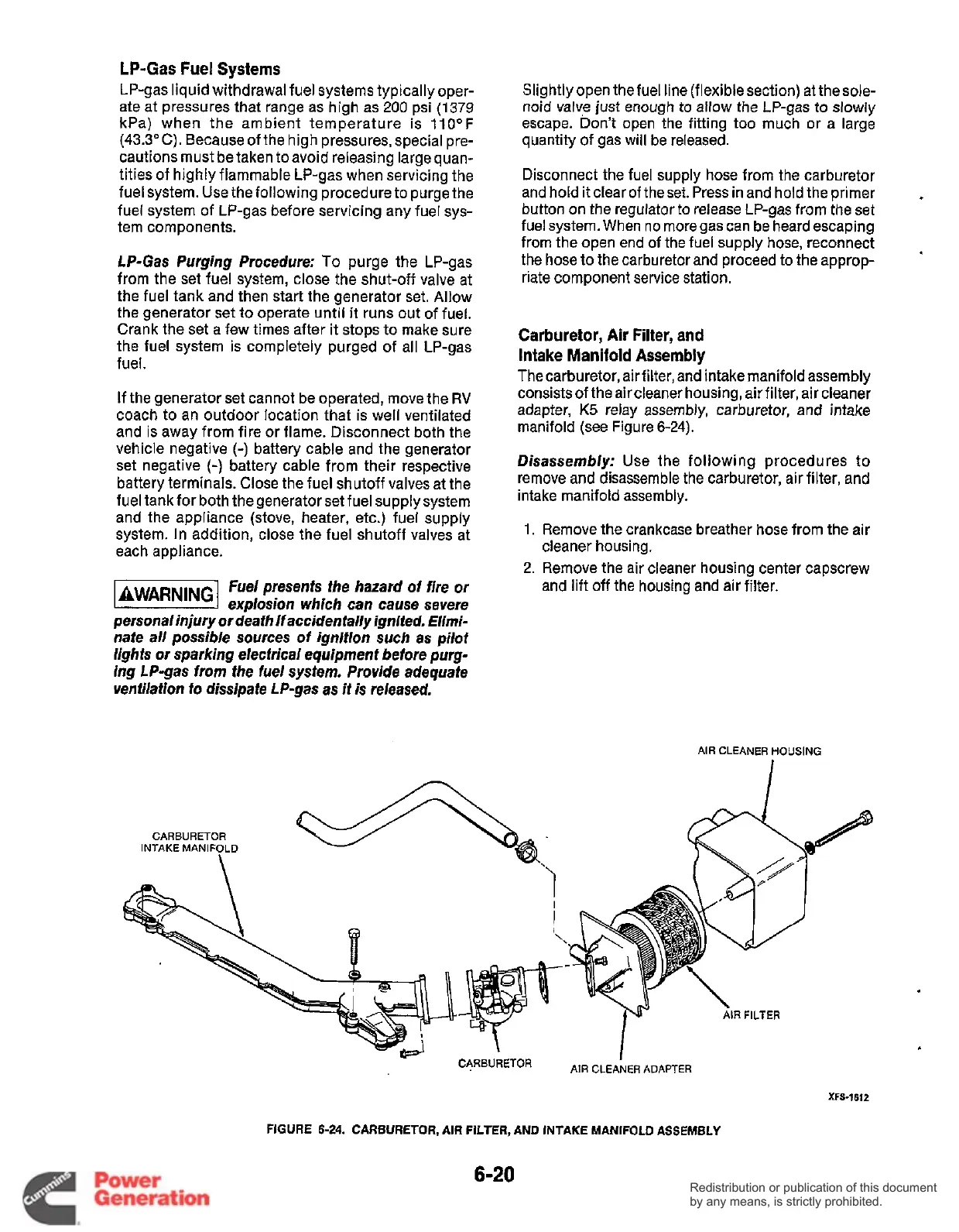
Carburetor, Air Filter, and
Intake Manifold Assembly
Thecarburetor, air filter, and intake manifold assembly
consists of the air cleaner housing, air filter, air cleaner
adapter,
K5
relay assembly, carburetor, and intake
manifold (see Figure
6-24).
Disassembly:
Use the following procedures
to
remove and disassemble the carburetor, air filter, and
intake manifold assembly.
1.
Remove the crankcase breather hose from the air
cleaner housing.
2.
Remove the air cleaner housing center capscrew
and lift off the housing and air filter.
AIR CLEANER HOUSING
XFS-1612
FIGURE
6-24.
CARBURETOR, AIR FILTER,
AND
INTAKE MANIFOLD ASSEMBLY
6-20
Redistribution or publication of this document
by any means, is strictly prohibited.
Redistribution or publication of this document
by any means, is strictly prohibited.