I-
I
.I
I
1
I
I
IB
I
I
I
I
I
I
IMP0
R
TA
N
T!
@%@%I
Due
to
the
pos-
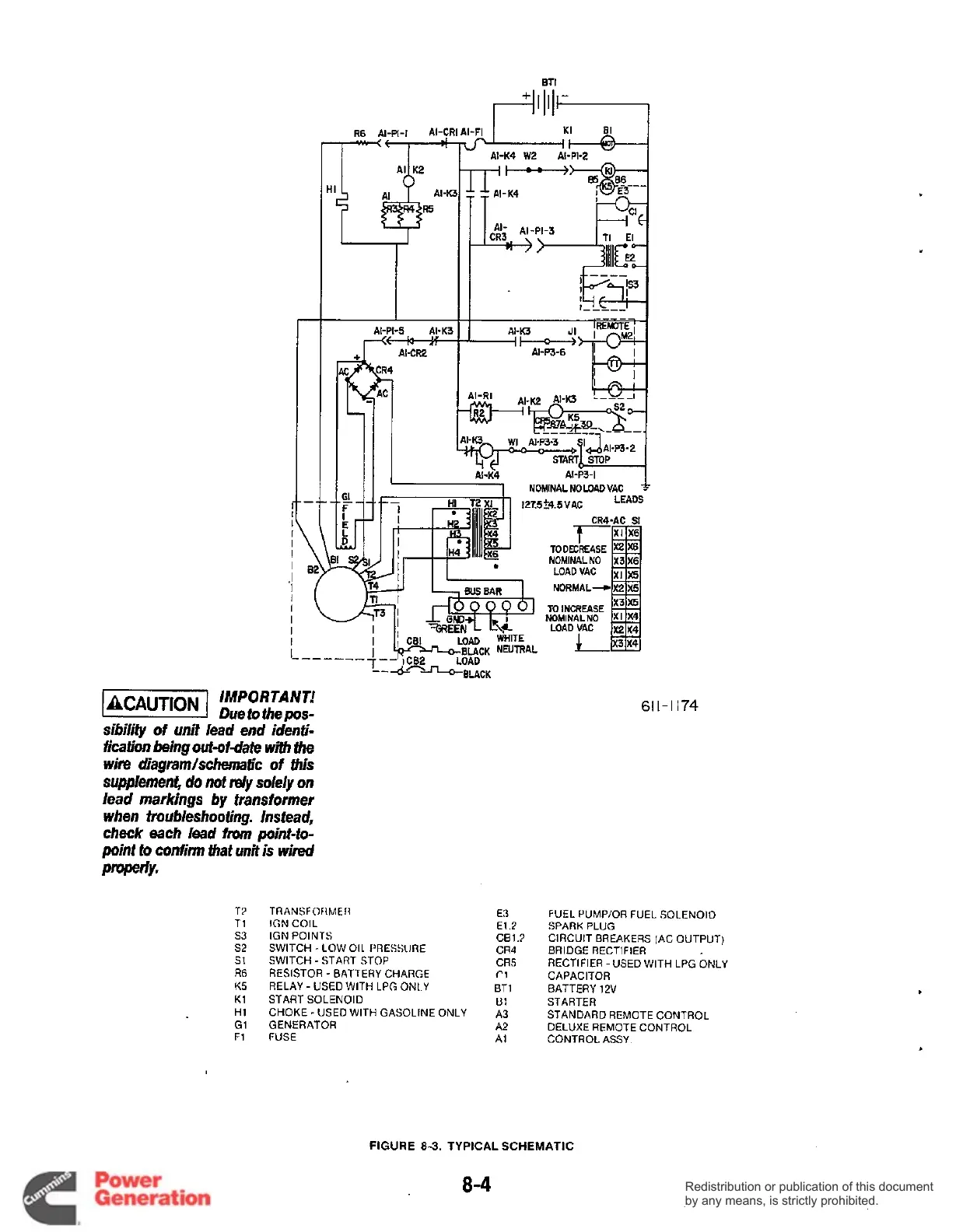
sibility of unit lead end identi-
fication being
out-ofdate
with
the
wire diagrarn/schematic
of
this
supplement,
do
not
rely
solely
on
lead markings by transformer
when troubleshooting. Instead,
check
each
lead
from
point-fo-
point
to
confirm that unit
is
wired
NOMNALNOLOADVAC
f
127.5%.5VAC
LEADS
r““
TODOCREASE
NOMINAL
NO
LOA0
VAC
NORMAL4
TO
INCREASE
NOMINALNO
LOAD VAC
L
1--
1CB2 LOAD
-----
--4-ELACK
TT
TI
s3
52
s1
R6
K5
K1
H1
G1
F1
TRANSFORMER
IGN COIL
IGN
POINTS
SWITCH
-
LOW
011
I’RESSIIRE
SWITCH -START STOP
RESISTOR
-
BATTERY CHARGE
RELAY
-
USED WITH
LPG
ONLY
CHOKE
-
USED WITH GASOLINE ONLY
START SOLENOID
GENERATOR
FUSE
E3
E12
CB1.3
CR4
CRS
f.1
BT
1
u:
A3
A2
A1
6
I
I
-
I I
74
FUEL PUMP/OR FUEL SOLENOID
SPARK
PLUG
CIRCUIT BREAKERS (AC OUTPUT)
BRIDGE RECTIFIER
RECTIFIER -USED WITH LPG ONLY
CAPACITOR
BATTERY
12V
STARTER
STANDARD REMOTE CONTROL
DELUXE REMOTE CONTROL
CONTROL ASSY
FIGURE
8-3.
TYPICAL SCHEMATIC
8-4
Redistribution or publication of this document
by any means, is strictly prohibited.
Redistribution or publication of this document
by any means, is strictly prohibited.