Output common to M1 (Internal power 0V)
Input common to P1 (Internal power 24V)
Output common to P1 (Internal power 24V)
Input common to M1 (Internal power 0V)
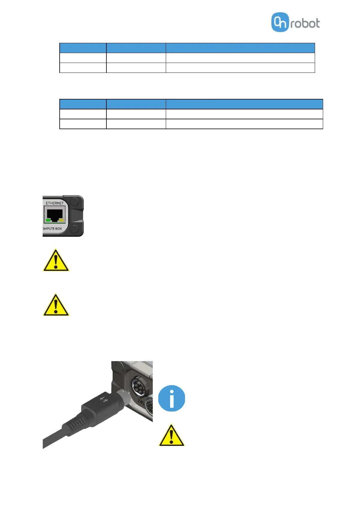
6.3.3 Ethernet cable
Connect the provided Compute Box (ETHERNET connector) and your computer with the
supplied UTP cable.
This connection is only needed for programming.
Use only original OnRobot ethernet cables or replace it with one
that is shielded and no more than 3 meter long.
Check and make sure that the Compute Box enclosure (metal) and the
robot controller enclosure (metal) are not connected (no galvanic
connection between the two).
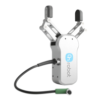
6.3.4 Power supply
Connect the supplied power supply to the Compute Box 24V
connector.
To disconnect the power connector, make
sure to pull the connector housing (where the
arrows are shown) and not the cable.
Use only original OnRobot power supplies.
Finally, power up the power supply that will power the Compute Box and the connected Tool(s).