Pulsar
2
Service Manual
OPTIKON 2000
Cod. 111004SEN
Rev.C
5-7
a square wave of variable duty cycle is output, the higher is the duty cycle the
higher will be the pump speed. The square wave is applied to U19
optocoupler that
replicates the same waveform at the input of U18B (U19 allows to maintain
electric separation between GNDs and GNDp). U18B is a three pole low-pass
filter, its output voltage is proportional to the duty cycle at the input.
- A watch dog circuit to monitor the microprocessor activity. In case of
microprocessor failure, this watch dog disables outputs of U6 and U16 TTL
latches that control system outputs, putting the PULSAR2 in a safe state.
- A serial DAC (MAX5250) that generates the dc voltages to control the
pressure preset of the air injection tamponade system and the preset of
Ultrasound power.
- The interface to the U/S and Diathermy driver board.
The lines to control the 347150 are (J1):
1. Tuning request (J1-7, active high)
2. Phaco on (J1-6, active low)
3. Pulsed mode and pulses frequency (J1-4)
4. ERR0 and ERR1 error lines (J1-3 and 5). These lines are both high if the
handpiece is ready to operate, 0-0 means no handpiece connected, 0-1
Please tune, 1-0 tuning failed, Check tip.
5. Diathermy on (J1-8)
6. Power level setting for phaco or diathermy (J1-1 and 2).
Trough the J10 connector, the Control board monitors the correctness of the
activity of the U/S and Diathermy driver board (Ultrasound and diathermy
emission) and can stop the power emission in case of fault.
4. Sheet 5/5 contains the electronics for control of the proportional valve and
the trimmers for its calibration.
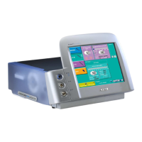
5.3 GRAPHIC USER INTERFACE
Display of parameters and data input is performed by a Graphic User Interface.
This device connects with the 393200 Control Board through a RS232 three wires
serial interface.
The relevant connector is J7. The Control Board and the GUI exchanges data using a
proprietary eight bit protocol. The correctness of data flow is continuously monitored by both
the Control Board software and the GUI software, a rotating logo in the lower part of the user
screen ensures that the two software are communicating properly.