Rear Panel
Page 10
AC240V
A 2696
Digita l (D AB +)
Intern et F M Tuner
12
RISK OF ELECTRIC
SHOCK DO NOT OPEN
C A U T I O N
DAB/ FM
DAB/FM
1 2
3
4
5
6
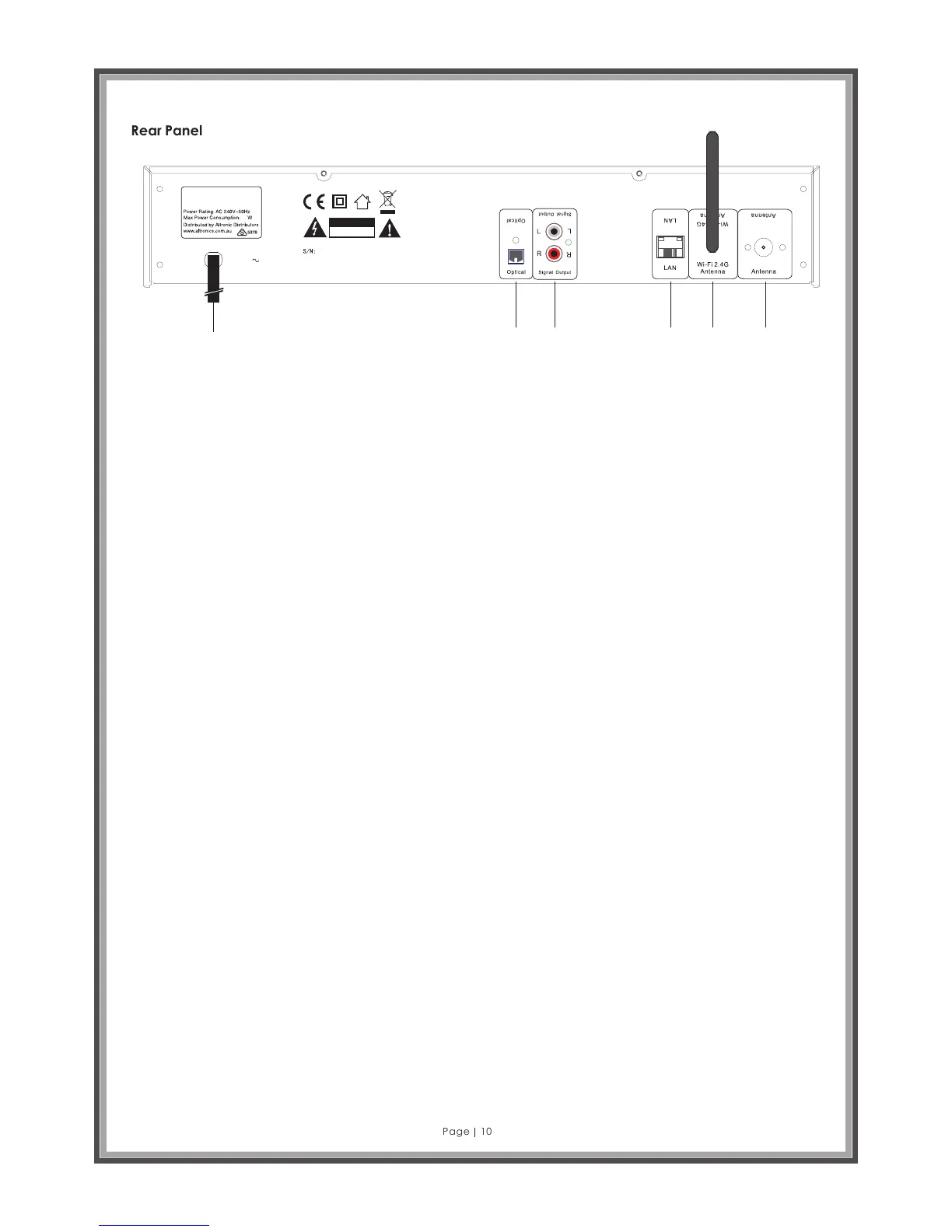
1. Power cord.
2. Optical: Connect an optical cable (not supplied) to connect to a digital input such as the optical input on
amplifiers.
3. Signal Output: RCA stereo ANALOGUE output connections. Connect RCA to RCA stereo pair cable
(supplied), ensuring the red connector on the cable is connected to the red connector on both the A 2696
and your amplifier.
4. LAN: Ethernet cable connection for connecting between the A 2696 and a router (UTP Cable not supplied).
5. Wi-Fi 2.4G Antenna: WLAN 2.4 GHz Wi-Fi antenna input jack for internet radio (supplied).
6. DAB/FM Antenna: 75 ohm Tuner antenna for both FM and DAB+ radio reception (supplied).
DESCRIPTIONS
Optical: Use this output to connect a digital amplifier using an optical cable (also known as an optical
waveguide or TOSlink). One of the advantages of digital transmission of the audio signal to the amplifier is that
interference cannot affect the signal and reduce the quality as can occur with analogue transmission. You can
also connect the optical input of a digital recorder to this output to save and then playback the audio.
This output uses the S/PDIF (Sony / Philips Digital Interface) protocol. This is a standard protocol for digital
transmission of audio signals, which is supported by just about any device with a digital interface. Before
making the audio connection to your amplifier, please make sure the volume is at a suitable level to prevent
damage to your hardware.
Signal Out: The line output on the back of the device is intended to be connected to the Line input of a Hi-Fi
amplifier or a pair of active speakers (speakers with built-in amplifiers). The output is designed for a voltage
level of 2 VRMS. Before making the audio connection to your amplifier, please make sure the volume is at a
suitable level to prevent damage to your hardware.
LAN: Use this port if you would like to integrate the A2696 into your network via a wired connection. To
distinguish it from the wireless or WLAN connection, it is frequently referred to as a LAN or Ethernet port. The port
supports data rates of 10 and 100 Mbps.
To connect the A2696 to your router in this manner, use a standard network cable (twisted pair with RJ45 plugs).
To connect the A2696 directly to your desktop PC or laptop, either use a network switch (also known as a
bridge) or a hub.
To connect the A2696 without any intermediate devices, use a crossover cable instead of a standard network
cable. Two LEDs near the port show the status of the link: orange indicates a live connection to the network
junction (node); network traffic is signalled by a green LED (usually flickering).
Wi-Fi 2.4 GHz WLAN Antenna: If you have access to a 2.4 GHz Wireless LAN (WLAN) router, screw the antenna
provided onto this connector. If possible, ensure that the antenna is set to a vertical position to ensure the best
possible reception.