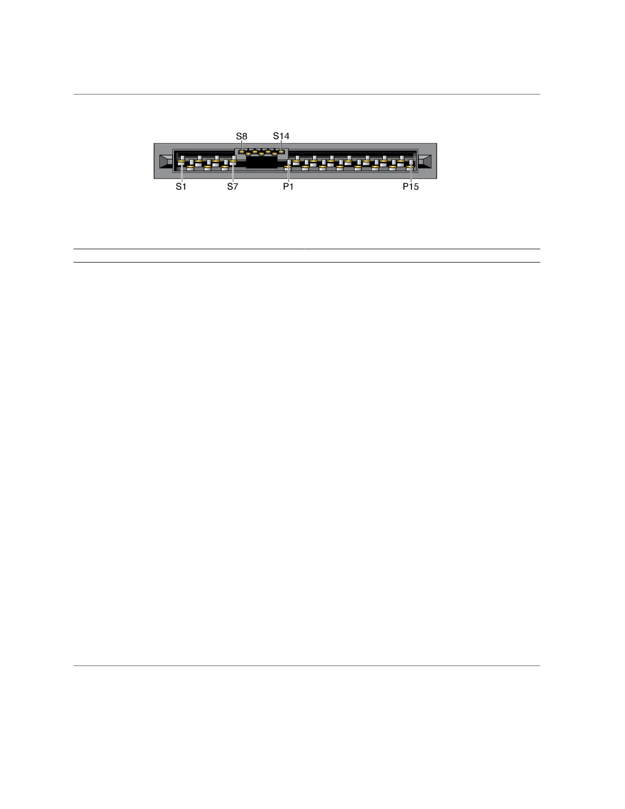
Identifying Ports
The following table lists the pinouts for the SAS connector.
Segment Pin Signal Note
S1 Gnd Second mate
S2 TX+
S3 TX-
Transmit from PHY to hard drive
S4 Gnd Second mate
S5 RX-
S6 RX+
Receive from hard drive to PHY
Signal segment
(S1 to S7)
S7 Gnd Second mate
S8 Gnd Second mate
S9
S10
S11 Gnd Second mate
S12
S13
Back-side signal
(S8 to S14)
S14 Gnd Second mate
P1 3.3V Not Supported
P2 3.3V Not Supported
P3 3.3V Not Supported
P4 Gnd First mate
P5 Gnd Second mate
P6 Gnd Second mate
P7 5.0V Pre-charge, second mate
P8 5.0V
P9 5.0V
P10 Gnd Second mate
P11 Reserved Should be grounded
P12 Gnd First mate
P13 12.0V Pre-charge, second mate
P14 12.0V
Power segment
(P1 to P15)
P15 12.0V
Powering On the Server for the First Time 59
 Loading...