a. Disconnect all cables from the back of the server.
b. If applicable, remove any additional Velcro straps that were installed to bundle the
cables.
c. Unwrap the six Velcro straps that are securing the cables.
d. Open the three cable covers to the fully opened position.
e. Remove the cables from the CMA and set them aside.
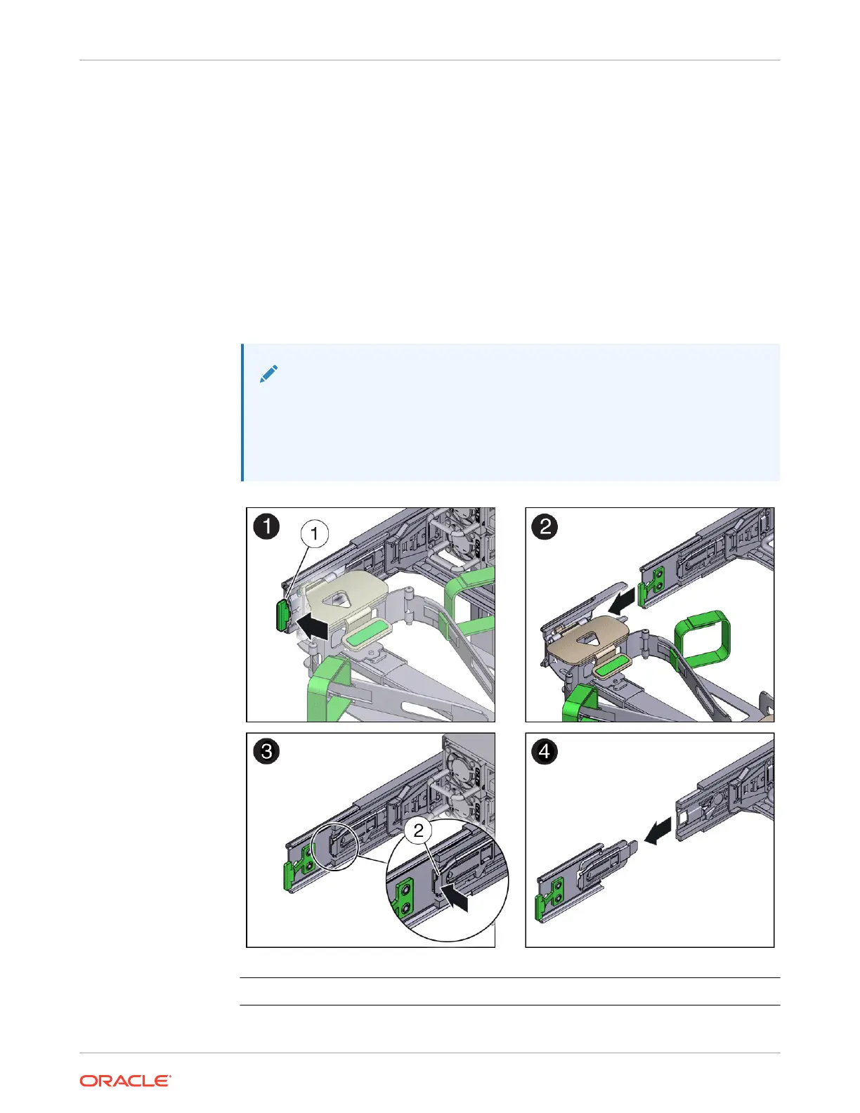
3. To disconnect connector D:
a. Press the green release tab (callout 1) on the slide rail latching bracket toward the left
and slide the connector D out of the left slide rail [1 and 2].
When you slide connector D out of the left slide rail, the slide rail latching bracket
portion of the connector remains in place. You disconnect connector D in the next step.
Note:
After you disconnect connector D, do not allow the CMA to hang under its
own weight. Throughout the remainder of this procedure, the CMA must be
supported until all the remaining connectors are disconnected and the CMA
can be placed on a flat surface.
Call Out Description
1 Connector D release tab (green)
Chapter 4
Replacing the Cable Management Arm
4-19