Call Out Description
1 Connector B release lever
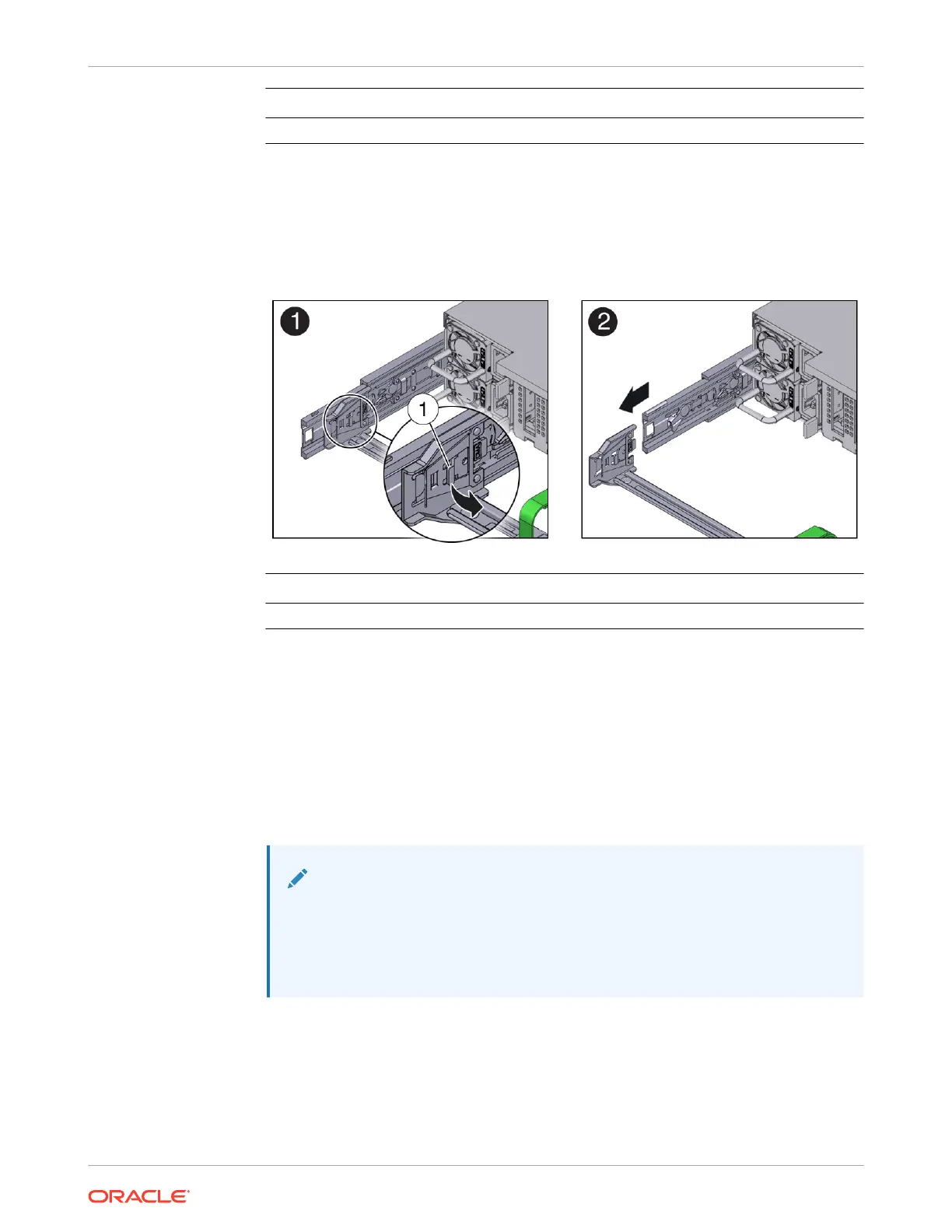
6. To disconnect connector A:
a. Place your left arm under the CMA to support it and grasp the back end of connector A
with your left hand.
b. Use your right thumb to pull the connector A release lever to the right, away from the
left slide rail (callout 1), and use your left hand to pull the connector out of the slide rail
[1 and 2].
Call Out Description
1 Connector A release lever
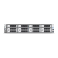
7. Remove the CMA from the rack and place it on a flat surface.
8. Go to the front of the server and push it back into the rack.
Install the Cable Management Arm
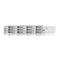
1. Prepare the CMA for installation.
a. Ensure that the flat cable covers are installed on the CMA.
b. Ensure that the six Velcro straps are threaded into the CMA.
Note:
Ensure that the two Velcro straps located on the front slide bar are threaded
through the opening in the top of the slide bar. This prevents the Velcro
straps from interfering with the expansion and contraction of the slide bar
when the server is extended out of the rack and returned to the rack.
c. To make it easier to install the CMA, extend the server approximately 13 cm (5 inches)
out of the front of the rack.
d. Take the CMA to the back of the equipment rack, and ensure that you have adequate
room to work at the back of the server.
Chapter 4
Replacing the Cable Management Arm
4-21