Note:
References to "left" or "right" in this procedure assume that you are facing
the back of the equipment rack.
Throughout this installation procedure, support the CMA and do not allow it
to hang under its own weight until it is secured at all four attachment points.
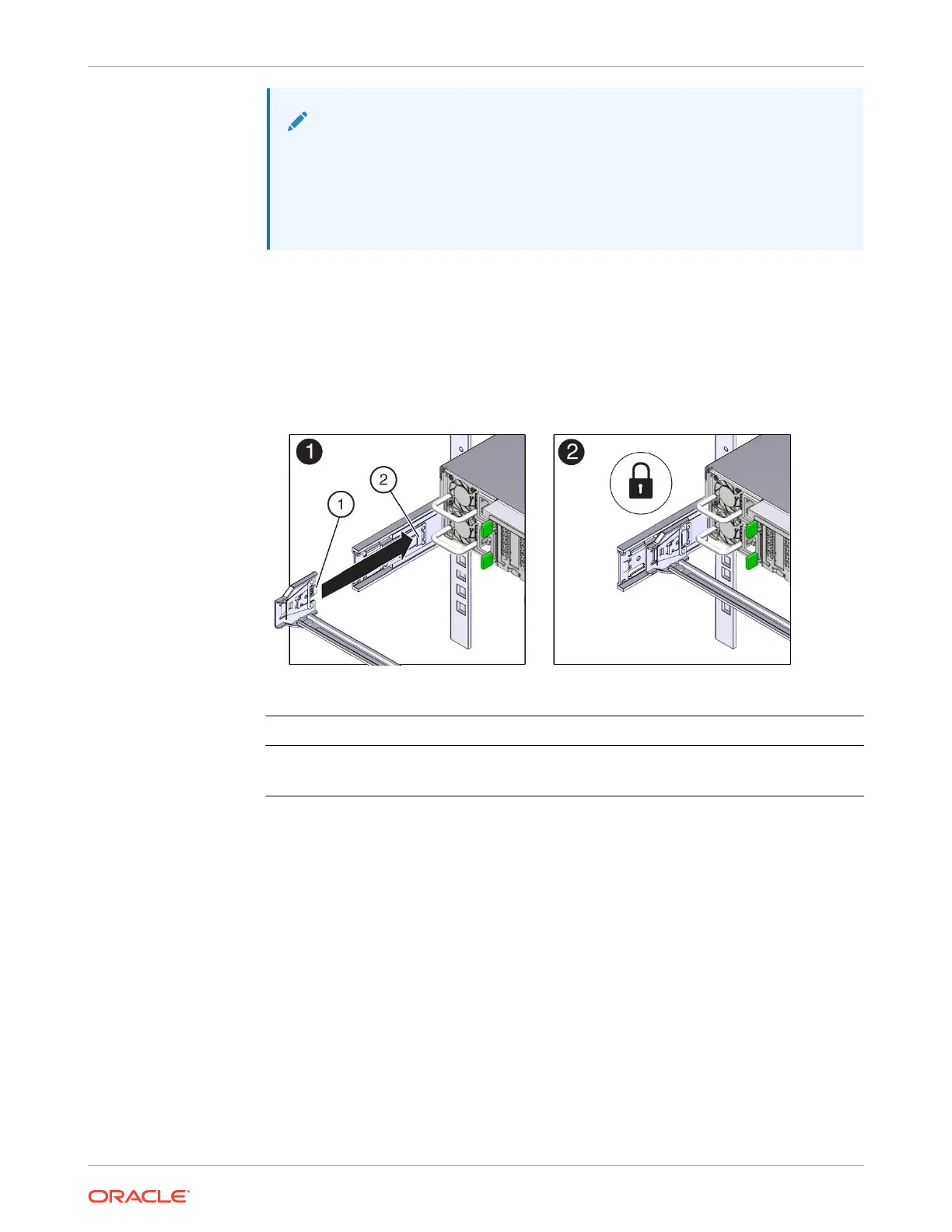
2. To install CMA connector A into the left slide rail:
a. Insert CMA connector A into the front slot on the left slide rail until it locks into place
with an audible click [1 and 2].
The connector A tab (callout 1) goes into the slide rail front slot (callout 2).
b. Gently tug on the left side of the front slide bar to verify that connector A is properly
seated.
Call Out Description
1 Connector A tab
2 Left slide rail front slot
3. To install CMA connector B into the right slide rail:
a. Insert CMA connector B into the front slot on the right slide rail until it locks into place
with an audible click [1 and 2].
The connector B tab (callout 1) goes into the slide rail front slot (callout 2).
b. Gently tug on the right side of the front slide bar to verify that connector B is properly
seated.
Chapter 4
Replacing the Cable Management Arm
4-22