Setup Procedure Perform Compass Offset
OceanTRx
TM
4-500 Installation and Operations Manual 7-13
Enter the 'naked-eye' estimate in the Offset field.
If the data latency (in seconds) is known, enter the latency in the Latency field. If
the latency is not known, leave the factory default setting of 0.060 seconds.
Click OK and then click [V] on the keyboard and press Enter to save.
3. Determine the antenna nominal azimuth:
Point the antenna to the desired satellite.
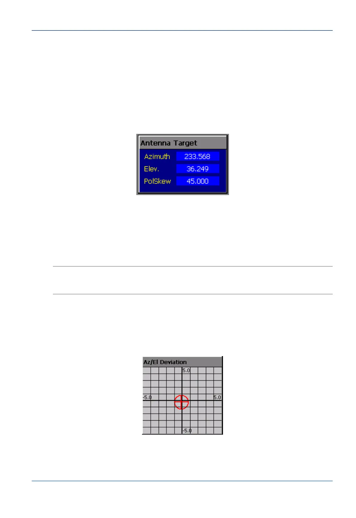
Write down the antenna’s azimuth as it appears in the Antenna Target window of
the Operation Screen. This will serve as your nominal azimuth. See the following
figure:
Figure 7-14: Antenna Target Window
4. Determine the antenna actual azimuth:
Using Manual Mode (see Section 8.1.10 Manual Mode on page 8-6), change the
antenna’s azimuth orientation until it points to the satellite.
The required amount of movement depends on the accuracy of your initial estimate
(a typical estimate will fall within ±10°).
NOTE: Use the Spectrum Analyzer Screen to determine when you are locked onto the satellite
(see Section 9.1 Once the satellite is acquired, set the antenna to Step-Track Mode (see
Section 8.1.4 Step-Track Mode on page 8-4).
5. Determine the azimuth deviation. This is the difference between the nominal azimuth
and the antenna’s actual azimuth.
You can use one of the following methods:
Observing the graphic Az/El Deviation window on the Operation Screen
calibrated up to ±5°.
Figure 7-15: Az/El Deviation Window
Running the Graphic Data Logger, which records azimuth deviation as a
parameter of the Antenna Step Track subgroup (see Section 9.2.1 Using the
Graphic Data Logger on page 9-10).


 To Next Page