VII. Device Operation
i. how to set the probe compensation
Before working the probe with any of input channels (Channel 1 / 2 / 3 / 4), better to adjust its
compensation, so as to assure ideal measurement effect. Following operation steps to adjust probe
compensation -
i) From PC software operation interface, mouse-click to get access to device function menu,
choose "Channel";
ii) then "CH1", set the "Probe Rate" at certain option (either x1, or x10, or x100, or x1000). Next, from
physical probe, switch the probe attenuation to the matching option correspondingly.
Note: The probe compensation setting from function menu will keep valid until new setting change introduces.
Caution:
The default probe compensation setting into PC software reads x10, before
working the probe with the device, making sure the probe compensation of both
places is matching.
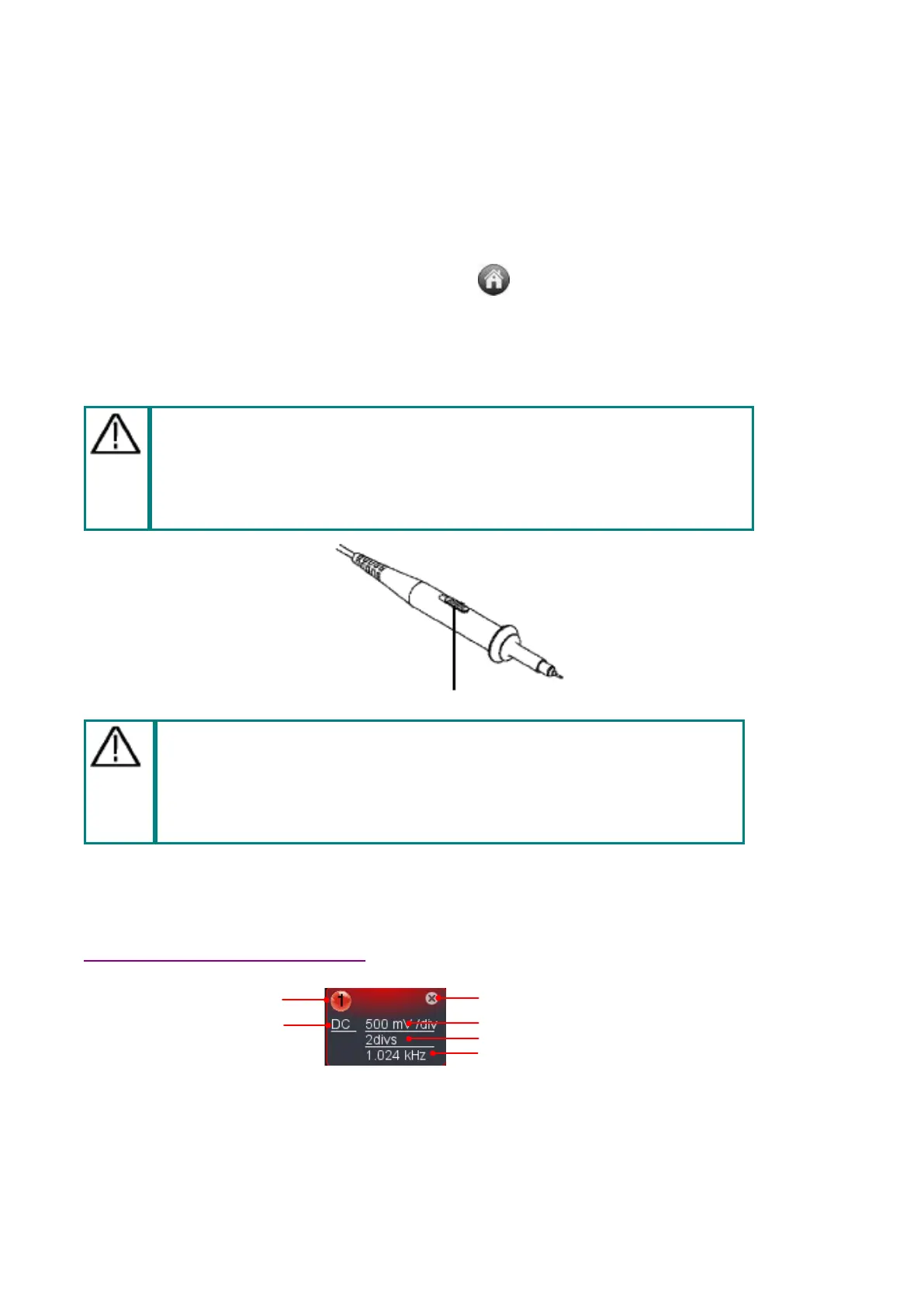
Figure VII-1. Probe Attenuation Switch Position
Caution:
For physical probe, when the compensation set in x1, the probe itself will
limit the device bandwidth at 5MHz.
To reach the full bandwidth, the physical probe’s compensation should be
set in x10, or above.
ii. how to set the vertical system from PC software
In “Channel extension window for Channel 1 / 2 / 3 / 4” (as item 20 / 19 / 18 / 17 described under
VII. Operation Interface of PC Software), related options of vertical system could be adjusted accordingly.
Current channel
Click to show/hide Channel menu
Click to turn on/off current channel
Click to switch coupling mode
Click to show voltage division combobox
Click to show zero point position slider bar
frequency counter
Through voltage divisions,
 Loading...