PlasmalabSystem100 Oxford Instruments Plasma Technology Installation Data
Installation Data (PECVD - TEOS)
Issue 10: February 11 Page 8 of 24 Printed: 10-Feb-11, 9:07
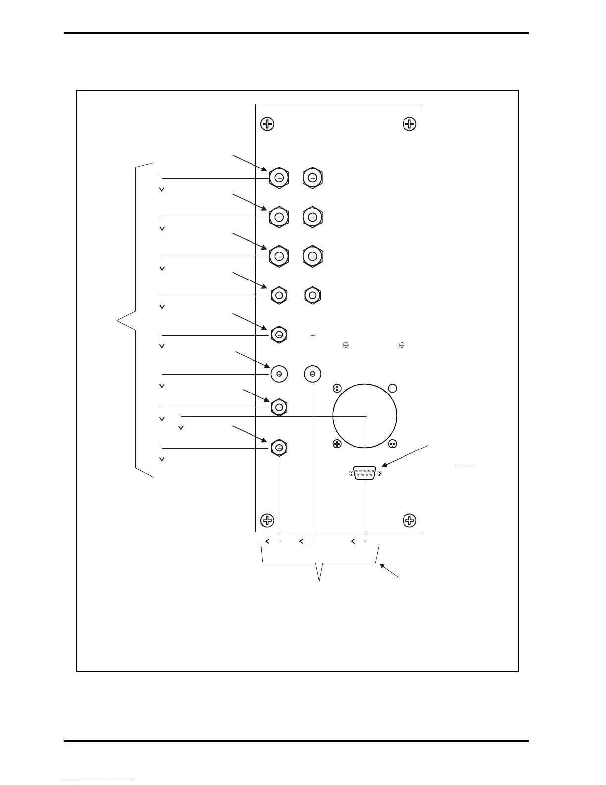
3. Services connections
711
738.5
746
781
816
851
886
921
956
Distance
to floor
level
385 415 461.5
3/8“ SWAGELOK
3/8“ SWAGELOK
3/8“ SWAGELOK
1/4“ SWAGELOK
1/4“ SWAGELOK
1/4“ VCR
(Additional
process gas
when required)
1/4“ VCR
TOP ELECTRODE
& AMU COOLING
OUTIN
OUT
IN
OUT
IN
OUTIN
LF GENERATOR COOLING
PROCESS CHAMBER
COOLING
TURBO COOLING
N2 IN
AIR IN
PROCESS
GAS
AIR OUT
CHAMBER BACKING
4 MM PUSH-FIT
LEGRIS
PLC SERVICE
ACCESS CONNECTOR
(THIS IS AN
ALTERNATIVE PC
COMMUNICATIONS
CONNECTION)
NOT
(Only used if
a turbo pump
is fitted)
(Only used if
chamber cooling
is fitted)
Distance
to left-hand
edge of frame
(viewed from rear
of system)
For the 3-frame system Automatic
Load Lock Services Panel, this
distance is 407 to the right-hand
edge of the frame (viewed from
rear of system).
For the 2-frame system Automatic
Load Lock Services Panel, this
distance is 1009 to the left-hand
edge of the frame (viewed from
rear of system)
Fig 4: PECVD services panel
NOTE: The Automatic load lock services panel is similar to that shown above but only
the CHAMBER BACKING connector is used.