Do you have a question about the Oxford Instruments OpAL and is the answer not in the manual?
Global support facilities to provide a co-ordinated response to customer queries.
Details of system identification through labels on the power box.
Lists attached Quality Control Forms (QCF) for system documentation.
Overview of health and safety information for system operation and maintenance.
Explanation of WARNING and CAUTION statements used in the manual.
Description of operating the system in service mode and associated precautions.
Details of hazards and associated warnings relevant to Health and Safety.
Detailed breakdown of specific hazards like Electrical, RF, Light, Temperature, Gases, etc.
Identification and meaning of various warning and advisory labels on the system.
Overview of services requirements for OpAL systems in appendices.
Reference to Appendix IDS for installation data sheets and services information.
Details on nitrogen supply for venting and purging, including check valve and vent line.
Description of the check valve function and its role in over-pressure relief.
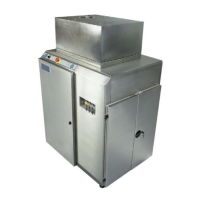
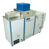
Overview of the OpAL system configuration and capabilities for ALD and PEALD.
Illustrations showing the locations of major system components.
Description of the hoist assembly for lifting and rotating the upper chamber.
Details on the PC 2000 software and PLC control of the system.
Description of controls and indicators on the base unit front panel.
Explanation of emergency off and interlock functions for safety.
Description of the process chamber arrangement and liners.
Description of the lower electrode, its grounding, cooling, and mounting.
Schematic and description of the vacuum system for the process chamber.
Location and details of the Power Distribution Unit and its components.
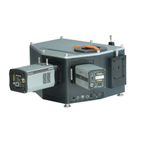
Description of the ICP 65 source, RF power, and gas supply connections.
Description of process gas handling systems, including non-toxic and toxic lines.
Information on precursor types, categories, and delivery methods.
Description of the N2 purged glove box and its incorporated features.
Details on the MKS Vision 1000-C residual gas analyser (RGA) for process monitoring.
Customer responsibility for installation and cabling, OIPT commissioning.
General guide for installing OpAL system components and customer safety.
Procedure for connecting all services, ensuring safety and proper setup.
Steps performed by OIPT for system commissioning, including checks and training.
Details on necessary adjustments based on system configuration, like pump purge.
Instructions for system operation, controls, indicators, and software.
Description of controls and indicators on the console front panel.
Overview of PC 2000 software facilities for controlling and monitoring the system.
Step-by-step procedure for initial system power-up.
Procedure for emergency shutdown, including stopping electrical power.
Procedures for routine shut down, power failure, software abort, and restart.
Procedure for opening and closing the process chamber using the hoist.
Procedures for operating the system, including screen savers and logging on.
Explanation of system alerts displayed by PC 2000 and their categories.
Functionality of the light beacon tower for system status indication.
Guide to accessing and using the PC 2000 software screens.
Procedure for pumping the system down to the required base pressure.
Procedure for safely venting the process chamber after purging.
Steps for performing a manual process run with specified parameters.
Procedure for executing an automatic process run using pre-defined recipes.
Instructions for running a complete automatic process with a single button.
Using production mode for simplified system operation with special recipe pages.
Guide to assembling, storing, creating, editing, and running recipes.
Overview of the Process Datalog facility for viewing process data runs.
Procedures for adjusting system parameters like N2 pressure and pump purge rate.
Functional descriptions of the PC 2000 software screens.
Schedule of periodic maintenance requirements for system components.
General weekly and monthly maintenance checks and procedures.
Monthly and annual maintenance procedures for the process chamber.
Monthly examination and cleaning of the substrate table.
Maintenance procedures for vacuum gauges, including capacitance manometer.
Mandatory requirements for gas handling system components like gas pods and MFCs.
Maintenance procedures for the pumping system, including filters and pumps.
Information on pump lubricating oils, including PFPE and hydrocarbon types.
Procedure for setting up the table heater temperature controller via auto-tune.
Contact information for global customer support facilities.
General guidance for troubleshooting, including pre-power-up checks.
Chart listing symptoms, possible causes, and actions for fault diagnosis.
Description of the emergency off chain and its routing for diagnostics.
General description of interlocks, enabling RF power and process gases.
Introduction to the Process Guide document and its included Glossary of Terms.
Information about plasma processes based on OIPT experience.
Requirements for installing process tools in a clean room environment.
Recommendations for OpAL system operation, including day-to-day and weekly checks.
Typical process operating ranges for ALD, ICP, precursors, and gas calibration.
Guidance for system uninstallation and disposal according to regulations.
Procedures for shutting down, disconnecting services, and dismantling components.
Guidance for system disposal at end-of-life according to local safety regulations.
Covers current requirements for measuring RF and microwave emissions.
Details on test meters and procedures for measuring field strengths.
Maximum permitted field strengths for RF and Microwave emissions.
Considerations for system design to prevent RF and Microwave emissions leakage.
Recommendations for observing maintenance and operating instructions for turbo pumps.
Instructions for re-greasing and relubrication of Alcatel ATP/ACT turbo pumps.
Information on OpAL systems to prepare the required environment for installation.
Details on system dimensions, weights, heat load, and sound level.
Diagrams illustrating OpAL services, views, and component layouts.
Details of services connections, including electrical, gas, and cooling.
Requirements for gas handling systems, including gas pods and process gases.
Specifications for electrical, water cooling, compressed air, nitrogen, and process gas supplies.
Information on available pump options, including dimensions and purge rates.
General description of interlocks and gas box interlock details.
Reference to precursor ordering guide for system setup.
List of OIPT global locations for support and sales.
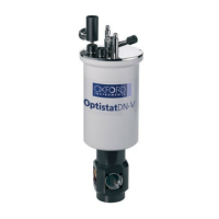
Information about the precursor pot fitted to the OpAL system.
Details on pot preparation and step-by-step procedures for bubbling.
Layout and procedures for pot preparation for vapour draw.
Description of rotameters, types, and full-scale flow values.
Procedure for setting N2 purge flow rates for pumps and other applications.
Graphs showing the relationship between flow rate and scale reading for rotameters.
Overview of services required for Plasmalab and Ionfab systems.
Requirements for clean room environment for process tool installation.
Recommendations for OpAL system operation and checks.
Operating ranges for ALD, ICP, precursors, and gas calibration.
Methods for applying cooling/warming water to OIPT systems.
Specifications for electrical supply, earthing, bonding, and circuit breakers.
Mandatory specifications for compressed air supply systems.
Mandatory specifications for Nitrogen supplies for venting and purging.
Mandatory specifications for process gas supplies.
Mandatory requirements for rotary pump, gas pod, and cryogenic pump extraction.
Specifications for the system environment, including temperature and humidity.
Health and Safety aspects of operating and maintaining the Automatch Unit.
Introduction to the Automatch Unit and its main versions.
Description of the main components of the Automatch Unit (AMU).
Control of the Automatch Unit via PC 2000 software, RF generator and automatch panels.
Typical layouts of matching components for RF generator matching.
Layout of the Sense and Control PCB for the AMU.
Procedures for testing and setting up the AMU, including disabling RF generators.
Adjustments for DC bias and Peak-to-peak switch settings.
Fault diagnosis chart for the Automatch Unit.
Factory default settings for incorrect link settings causing AMU malfunction.
Procedure for changing RF components, including padding capacitors.
Procedure for adjusting capacitor park positions when AMU is set to Auto.
Health and safety information for operating and maintaining the ozone delivery system.
Specifications of services required for Plasmalab and Ionfab systems.
General description of the ozone delivery system and its main parts.
Procedures for installation and commissioning of the ozone delivery system.
Instructions for operating the ozone delivery system via PC2000 and recipes.
Maintenance checks and troubleshooting guide for the ozone delivery system.
| Category | Laboratory Equipment |
|---|---|
| Manufacturer | Oxford Instruments |
| Model | OpAL |
| Application | Spectroscopy, Microscopy |
| Customization | Yes (application specific) |