OpAL Oxford Instruments Plasma Technology System Manual
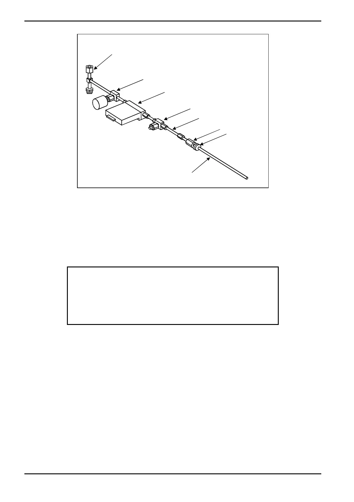
GAS IN TUBE
(STAINLESS STEEL)
GROMMET
2 µm FILTER
GAS LINE EXTENSION
FERRITE CORE
MASS
FLOW
CONTROLLER
GAS OUT
MANIFOLD
OUTLET SHUT-OFF
VALVE
(PNEUMATICALLY
CONTROLLED)
Fig 3-30: 94-81-9-11 Standard non-toxic gas line
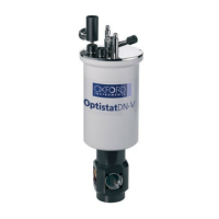
3.12.2 Standard toxic gas line
The standard toxic gas line is shown in Fig 3-31. All gas fittings are VCR and all stainless
steel pipework connections are welded. The gas in tube passes into the side of the gas
pod case, protected by a grommet.
Gas from the customer’s cylinder/regulator/filter flo
ws into the ‘gas in’ tube to the filter.
WARNING
THE CLOSED INLET VALVE REMAINS SHUT FOR DIFFERENTIAL
PRESSURE UP TO 210 BAR. A FAILURE UPSTREAM WHICH PRODUCES
LINE PRESSURES ABOVE THIS WILL NOT BE CONTAINED. IF THIS
PRODUCES A HAZARD, THE CUSTOMER IS WARNED TO FIT
ADDITIONAL PROTECTION UPSTREAM.
With the Inlet Valve and Outlet Valve open and the Bypass Valve closed, the gas flows
thro
ugh the 2 µm filter to the mass flow controller (MFC). The MFC controls the flow of
gas as commanded by the system controller. The gas then flows through the outlet valve
and into the gas out manifold where it is mixed with the other process gases before
flowing into the process chamber.
With the Bypass Valve open, the gas flows through the bypass line directly to the gas out
manifold. This facility is provided to enable the toxic gas line to be evacuated by pumping
down the process chamber. This is necessary to prevent air entering the gas line and
contaminating it during a gas cylinder changeover, and to service the gas line in the event
of an MFC or filter blockage.
Description
Issue 1: August 07 Page 3-36 of 46 Printed: 07 August 2009 07:42