lé^i= lñÑçêÇ=fåëíêìãÉåíë=mä~ëã~=qÉÅÜåçäçÖó= System Manual
b) Control and status panels for the process chamber. The Control and status panel has
associated EVACUATE, STOP and VENT buttons.
i) EVACUATE button: Select to pump-down the associated chamber.
ii) STOP button: Select to stop either pumping down or venting the
process chamber.
iii) VENT buttons: Select to vent the associated chamber.
c) Mimics of all valves showing open/closed status (coloured green when open, red
when closed).
d) Rotary pump control. Clicking on the EVACUATE button will switch the pump on (a
running rotary pump is indicated by animation).
e) A SET BASE PRESSURE button. Select to set the Process Chamber Base Pressure.
f) Context related message panel for the process chamber.
g) Purge cycle panel. Enter the required number of process chamber pump/purge cycles
required (a maximum of 100 cycles can be performed at a single time). The number
of purge cycles remaining is displayed. Note that the pump/purge times are set on
the tolerances page.
RKNMKO pÉêîáÅÉ=ãçÇÉ=é~ÖÉ=
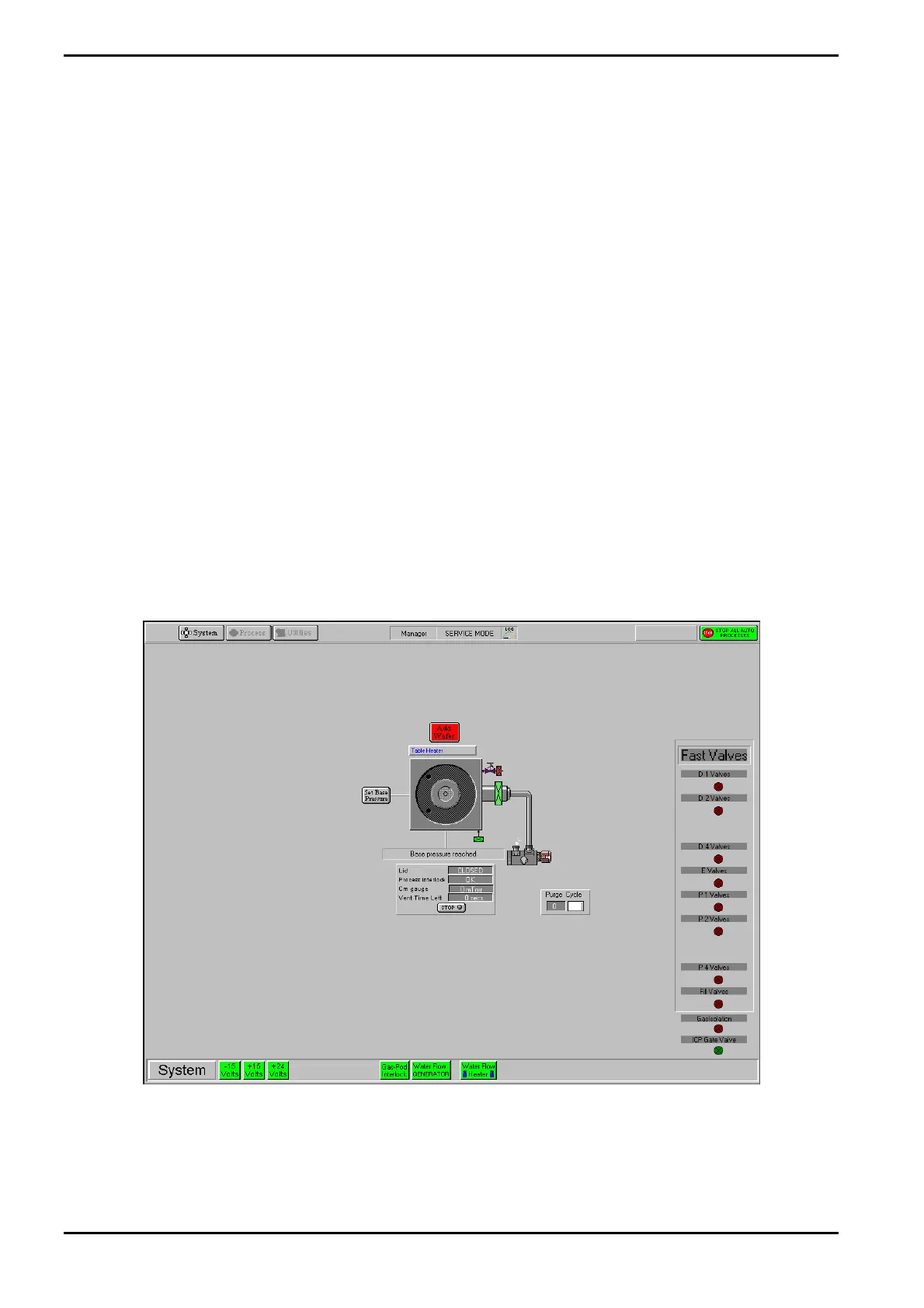
The Service Mode page is displayed by selecting the System button, then the Service option.
Fig 5-13: Service mode page
This page is used during maintenance to manually control system components.
Manual control of the following features is available by clicking on them (confirmation is
requested before any action is carried out):
Operating Instructions
Generic (OpAL Plasma) Issue 1: Oct. 07 Page 5-38 of 60 Printed: 06 November 2007 09:42