Installation Data Oxford Instruments Plasma Technology OpAL
4. Services connections
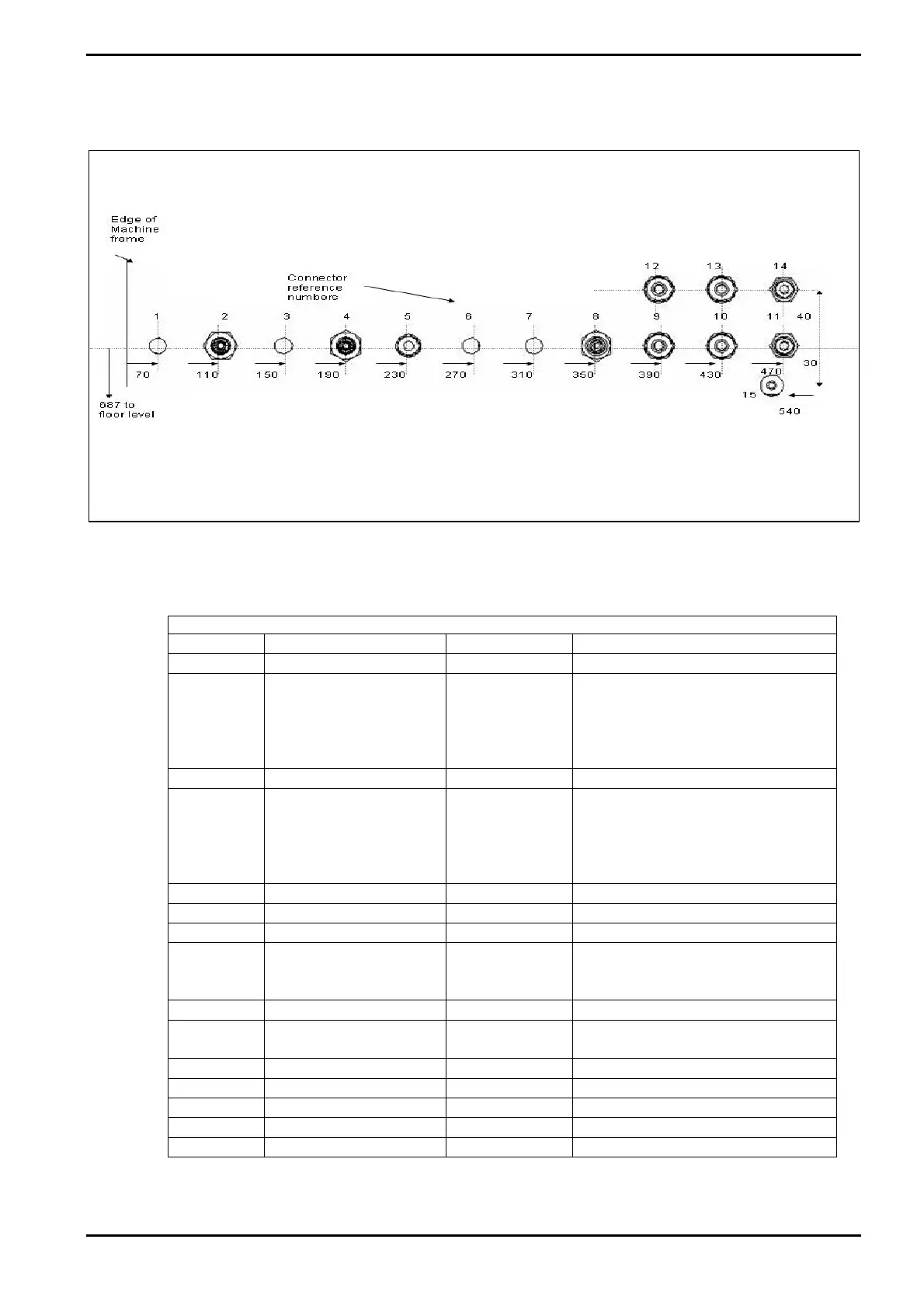
Fig 9: Services connector locations
NOTE: When installing the services, read the Mandatory requirements in the Services
Specification document.
ALD Machine with External Gas Pod
Connector
Service Fitting NOTE
1 Spare
2 Inert Purge gas IN ¼” VCR Either Argon or Nitrogen purge
for gas line located inside of
system cabinet. See section 6
For gas supply pressure and
flow requirements.
3 Spare
4 Argon Bubbler gas IN ¼” VCR Argon for bubbling gas line
located inside of system
cabinet. See sub-section 6.5 for
gas supply pressure and flow
requirements
5 N
2
vent gas IN ¼” Swagelok
6 Spare
7 Spare
8 Process gas IN ¼” VCR Only used to link external gas
pod to system. For internal gas
lines refer to Fig 8, page 12.
9 Electrode Cooling IN
3
/8” Swagelok
10 Electrode cooling
OUT
3
/8” Swagelok
11 Compressed air OUT 6mm Push-fit
12 Spare
13 Spare
14 Compressed air IN 6mm Push-fit
15 Drip tray Outlet ¼” OD pipe
Table 1: Services connector identification
Installation Data
Printed: 7-Aug-09, 8:03 Page 13 of 22 Issue 3: October 08


 To Next Page