OpAL Oxford Instruments Plasma Technology System Manual
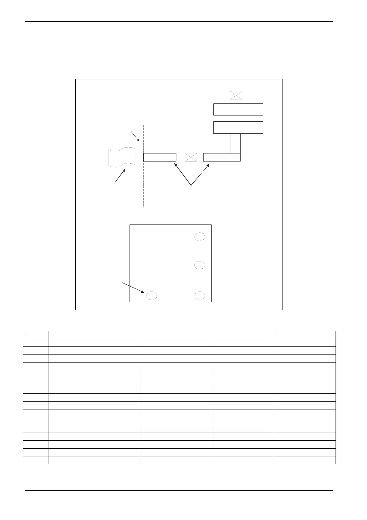
3.4.4 Heating
The management of condensation and decomposition in OpAL is achieved by dedicated
temperature control of individual components. Up to 16 temperature zones are available
as shown in Fig 3-16 and Table 3-1. Temperature is controlled using PID.
Zone 1
Zone 2
Services panel
Gate
Va l v e
ICP
Gate Valve
Zone 4
External pumping
4 x 0.5 m lengths
Zone 3
Precursor 1
Reserved for water
Zone 5
Precursor 2
Zones 6, 7, 8
Precursor 3
Precursor 4
Zones 9, 10,11
Zones 12,13,14
Fig 3-16: Temperature zones
Zone Name Temp Range (deg C) Power (Watts) Snap switch
1 Upper Chamber 20 - 180 2000 200 ± 10
2 Lower Chamber 20 - 180 2000 200 ± 10
3 Internal pumping 20 - 120 75 160 ± 10
4 External pumping 20 -120 4 x75 160 ± 10
5 P1 –Water Z3 (dual valve) 20 - 200 84 220 ± 10
6 P2Z1 (source pot) 20 - 200 87 220 ± 10
7 P2Z2(intermediate) 20 - 200 74 220 ± 10
8 P2Z3(dual valve) 20 - 200 84 220 ± 10
9 P3Z1(source pot) 20 - 200 87 220 ± 10
10 P3Z2(intermediate) 20 - 200 74 220 ± 10
11 P3Z3(dual valve) 20 - 200 84 220 ± 10
12 P4Z1(source pot) 20 - 200 87 220 ± 10
13 P4Z2(intermediate) 20 - 200 74 220 ± 10
14 P4Z3(dual valve) 20 - 200 84 220 ± 10
15 ICP Gate Valve 20 - 120 162 160 ± 10
16 Spare 20 - 200 220 ± 10
Table 3-1: Temperature zones
Description
Issue 1: August 07 Page 3-16 of 46 Printed: 07 August 2009 07:42