System Manual Oxford Instruments Plasma Technology OpAL
3.9 Vacuum system
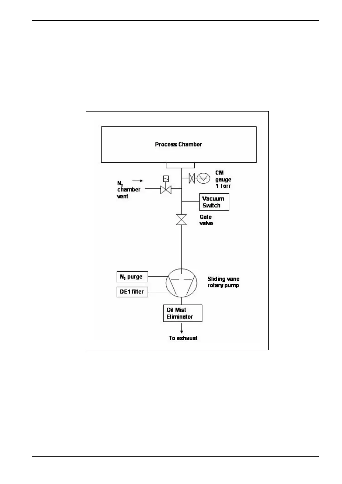
A typical vacuum schematic for the process chamber, using a 63m3/hr rotary with 2
metres of NW40 flexible stainless steel tubing, is shown in Fig 3-27. The gate valves and
isolation valves associated with the pumping systems are pneumatically operated.
The process chamber pressure is monitored by a 1-Torr capacitance manometer gauge.
Pressure control is achieved by flowing inert gas using a mass flow controller controlled
by PC 2000 via t
he Programmable Logic Controller (PLC).
Fig 3-27: Vacuum system
Description
Printed: 07 August 2009 07:42 Page 3-31 of 46 Issue 1: August 07