System Manual= lñÑçêÇ=fåëíêìãÉåíë=mä~ëã~=qÉÅÜåçäçÖó= lé^i
léÉê~íçê=áåíÉêÑ~ÅÉ=
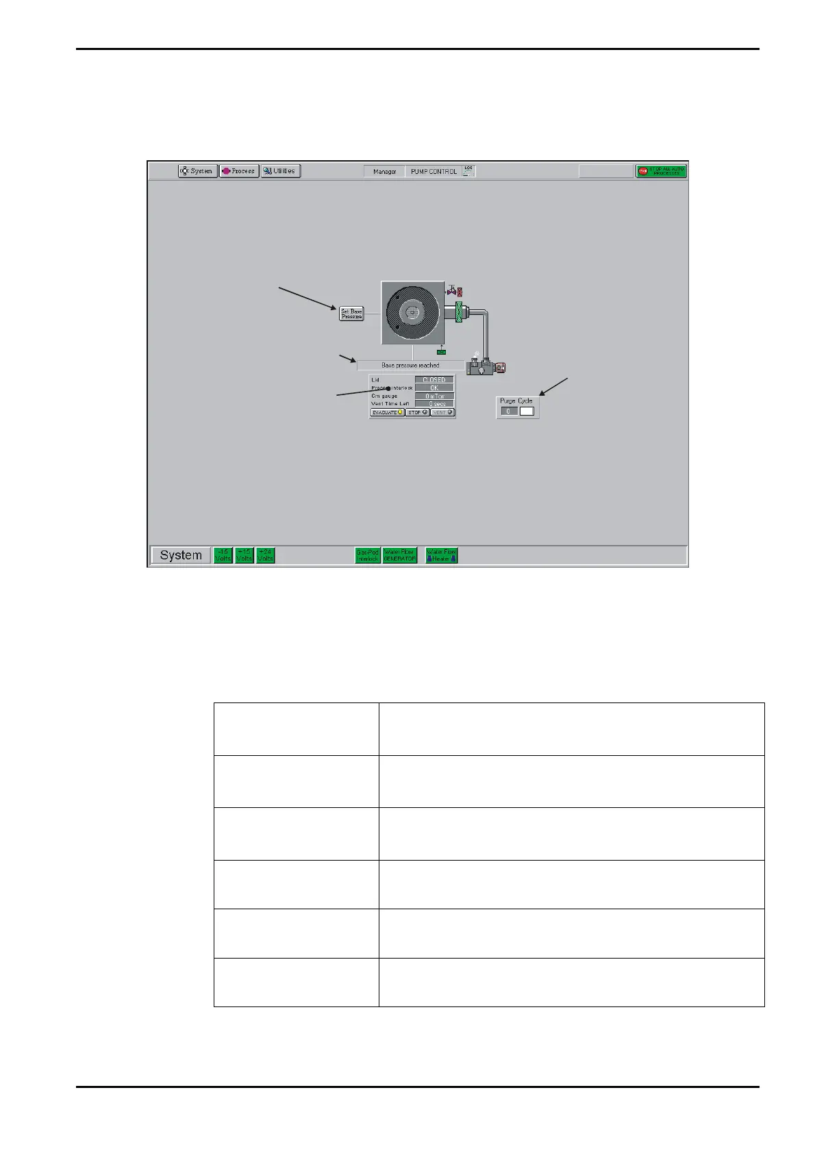
The Pump Control page Buttons, controls, indicators and message panels to allow you to
control the vacuum system are shown in Fig 5-12.
Process
chamber
status panel
Process chamber
message field
Purge cycle
panel
Click to set
Process Chamber
Base Pressure
Fig 5-12: Pump control page operator interface
The operator interface facilities are labelled in Fig 5-12.
The following facilities are provided:
a) System status indicators:
PSU:
Green when the -15V, +15V and +24V dc supplies are
healthy. Red when a supply is faulty.
N2 Vent Gas:
(If fitted)
Green when the N2 vent gas supply is healthy. Red when
the supply if faulty.
Gas Pod Interlock:
Green when the Gas Pod cover is fitted correctly. Red
when the cover is off.
Water Flow
GENERATOR:
Green when cooling satisfactory. Red when flowswitch is
tripped (i.e. cooling flow rate out of tolerance).
Water Flow HEATER:
Green when cooling satisfactory. Red when flowswitch is
tripped (i.e. cooling flow rate out of tolerance).
Pump Purge Switch:
(If fitted)
Green when the pump purge is switched on. Red when it
is switched off.
Operating Instructions
Printed: 06 November 2007 09:42 Page 5-37 of 60 Generic (OpAL Plasma) Issue 1: Oct. 07