Installation Data Oxford Instruments Plasma Technology OpAL
8.2 Gas box interlocks
Refer to drawing: SE81B26657 (PC2003 gas pod loom).
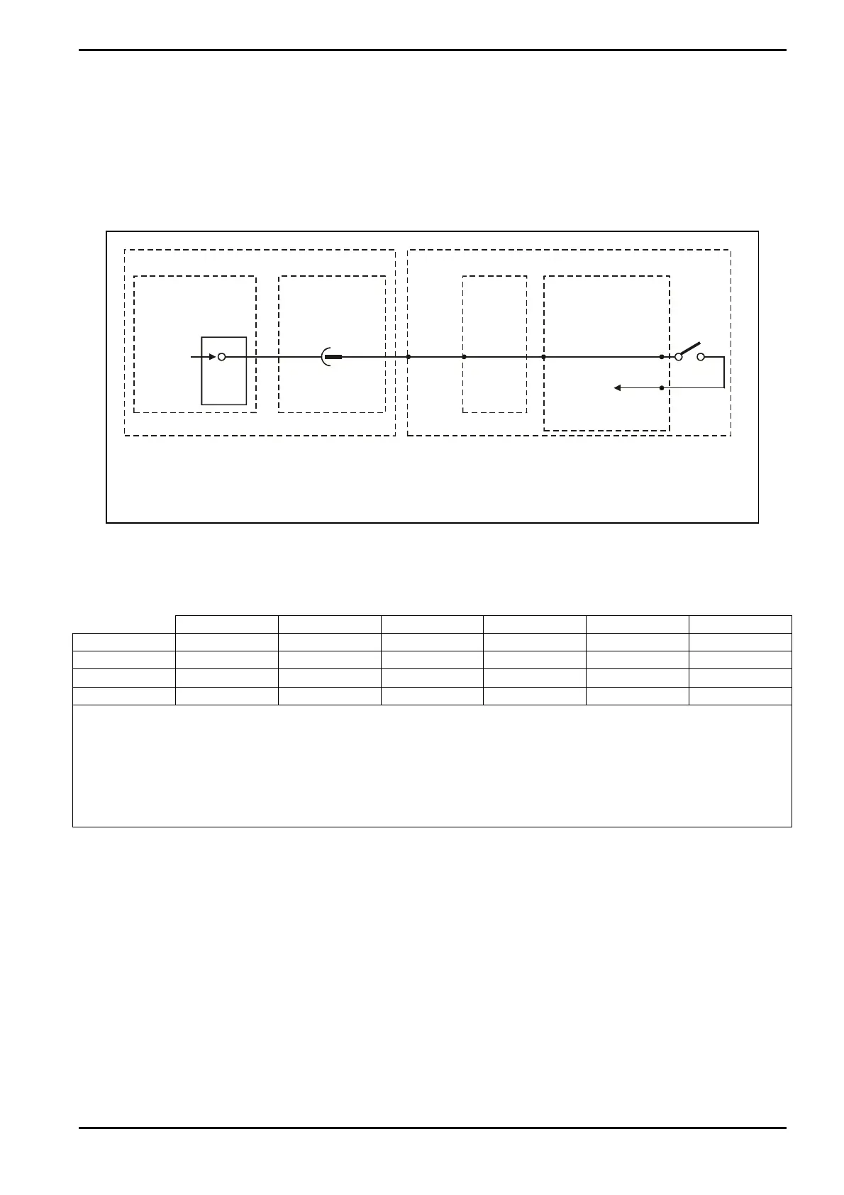
To enable process gases, the interlock chain must be complete. The gas box interlock is
shown in Fig 12.
1
BLK
20
24VDC
LID
SWITCH
PCB 94-PC00S26866 REAR SERVICES
PANEL
SKT25W
PIN4
PL25W
PIN4
GAS BOXSYSTEM CONSOLE
SERVICES
PANEL
SKT25W
PIN4
PL24W
PIN4
PCB 94-PC81S26655
JP6
PIN1
JP6
PIN2
JP6
PIN3
ia JP3 to CAN unit
controlling gases 1 - 4.
See NOTE.
NOTE: The function of the signal is to supply
24Vdc power to the digital outputs of
the CAN unit. The interlock continues
through idendical boards (where fitted)
which drive gases 5 - 8 and 9 - 12.
Fig 12: Gas box interlock chain
8.2.1 Incompatible gases
1
st
PCB Gas 2
nd
PCB Gas 3
rd
PCB Gas Type A Type B Type X
1
st
Gas 1 5 9 LK3A + 4 LK3B LK3A
2
nd
Gas 2 6 10 LK5A + 6 LK5B LK5A
3
rd
Gas 3 7 11 LK7A + 8 LK7B LK7A
4
th
Gas 4 8 12 LK9A + 10 LK9B LK9A
Gases are designated as one of three types:
Gas type A: Typically oxidising gases (e.g. oxygen)
Gas type B: Typically fuel gases (e.g. hydrogen)
Gas type X: Gases normally miscible with most other gas types.
If ANY gas Type A is enabled, then ALL gas Type B lines are disabled.
The gas box has a facility to prevent incompatible gases from being enabled
simultaneously, using soldered links.
Installation Data
Printed: 7-Aug-09, 8:03 Page 21 of 22 Issue 3: October 08